Writing Scalable Firmware: Implementing the Command Pattern in C++
In this article, we will review the basic concepts of this pattern—adapted to the context of our embedded systems—and then we will build a practical, straightforward example: an LED controlled via commands. Through this simple example, I’ll explain the pattern clearly so you can adopt it immediately in your own projects.
Tabla de contenidos
- What’s it and what do I need it?
- The Command Design Pattern
- Methodology
- Basic Example
- Source Code and Complete UML Diagram
- Before We Finish
- Apendix: Complete code just in case you don’t want to drive to Github
What’s it and what do I need it?
In embedded systems, we always start with something simple: a few buttons, a couple of states, and direct actions. But all it takes is for the project to grow a little bit, and suddenly, that button that used to just turn on an LED now has to do something completely different depending on whether an automatic door is opening, closing, paused, or waiting for a sensor signal. Without realizing it, the code turns into a spaghetti mess of if-else statements that nobody wants to touch. Let’s be real—we’ve all been there.
The problem isn’t the buttons themselves; it’s that a single button can mean different things depending on the system’s state. When we try to handle everything with conditionals, the code becomes a nightmare: scattered, duplicated, and fragile.
This is where the Command Software Design Pattern offers us an elegant alternative:
- It encapsulates actions.
- It separates decisions from behavior.
- It allows mapping states to commands without infinite branching.
The result is code that is easy to understand, easy to maintain, and scales naturally.
Although this pattern is often discussed in the context of desktop applications, its utility in embedded systems is far greater than one might think. After all, our day-to-day work revolves around issuing and executing commands:
- Turning an LED on or off.
- Adjusting a motor’s speed.
- Moving an actuator to a specific position.
- Triggering an initialization routine.
- Executing a sequence of commands.
Every interaction—no matter how simple it seems—follows the same pattern: someone asks for something to happen, and something in the system responds.
If we strip this mechanism down to its basic elements, we always find the same three actors:
- Invoker: The one issuing the order (I’ll refer to this as the sender).
- Command: The encapsulated order itself.
- Receiver: The one that finally executes the action.
In practice, these three often appear tightly coupled. It’s normal: it works, it’s direct, and it’s easy to program because you don’t have to think too much. But as soon as the same sender needs to produce different actions based on context, or when different sources need to generate the same order, that coupling stops being useful. And if you need to create a chain of commands… the nightmares begin.
These scenarios are anything but theoretical; we face them every day. For example:
- A single button with multiple behaviors depending on the system state (Button A does one thing in State X, but something different in State Y).
- The same command issued from different sources: A physical button, an interrupt, or a message received over the Internet.
- Complete sequences of actions that must execute in order for a single peripheral (a sort of macro-instruction).
- «Undo» functionality, which becomes incredibly useful when an operation needs to be reversed or canceled.
Do you recognize any of these cases? If they sound familiar, it’s because you are already in the domain of the Command Pattern.
The Command Design Pattern
The Command Pattern allows us to separate the three aforementioned actors (Invoker, Command, and Receiver) into independent objects. Its central idea is very simple: the command, action, or instruction we want to execute is encapsulated as an object. Nothing more, nothing less.
This separation is carried out as follows:
- The Invoker requests the execution of a command but knows neither the concrete action nor the receiver that will carry it out.
- The Command encapsulates the action and only knows the receiver, never the invoker.
- The Receiver executes the action but doesn’t know who requested it.
Thanks to this crystal-clear division of responsibilities, the same button can execute different actions, and the same action can be triggered by a button, a timer, or a message received via the Internet.
The official definition of this pattern is:
“Encapsulate a request as an object, thereby letting you parameterize clients with different requests, queue or log requests, and support undoable operations.”
If we pay attention to the last part of the definition, we’ll notice that it is possible (though not mandatory) to undo operations: undo the last addition, undo the last drawn shape, undo the last movement of a robotic arm, etc. It’s the equivalent of Ctrl-Z on your computer.
And if we focus on another part of the definition—queue or log requests—we realize that we could build lists of commands. Interesting, right?
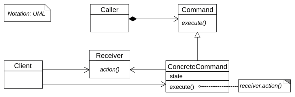
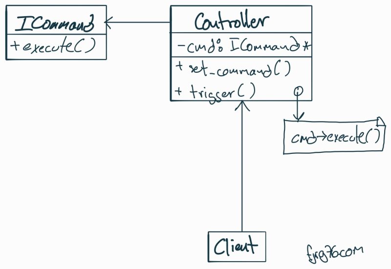
Before finishing this section, let’s look at the UML diagram for this pattern (courtesy of Wikipedia). Don’t let it intimidate you. We are about to build our own, step by step, as we develop the base example. By the time we finish, you’ll be on your way to becoming an expert in this pattern (considering that in future articles, we will be studying slightly more complex applications and examples).
Methodology
We often perceive the Command Pattern as more complex than it really is. Not because its elements are difficult individually, but because it involves several actors working together, each with specific responsibilities. That interaction—rather than the amount of code—is what can generate confusion the first time we study it.
That is why, in this series of articles, we will move step by step, calmly and in order—both for your sake and for «myself from the future», who will surely appreciate having this journey well-documented.
- Today’s installment: We will start by implementing the pattern in its most essential form: the classic version proposed in the GoF Design Patterns book. We will work in plain C++, without modern extensions or exotic optimizations that might distract us. No templates to eliminate dynamic polymorphism or similar «modernisms» just yet; first the classic, the direct, the didactic.
- Second article: We will build a macro, that is, a sequence of commands that execute one after another as soon as a single virtual button is activated.
- Third article: We will see how to undo actions performed.
Basic Example
To explain this pattern, I’m going to use a different approach than the thousands of tutorials found on the Internet (and in books). Instead of starting with the pattern definition, class hierarchies, or UML diagrams—which tend to intimidate more than they help—we are going to start directly from the main() function.
This way, you will be able to identify the actors in context, exactly as they are used in a real application. In other words, instead of the traditional bottom-up approach (from the pattern to the application), here we will work top-down: from the application to the pattern.
At the same time, always accompanied by the code, we will build our own UML diagram, element by element. I believe this approach is more educational and much less overwhelming than staring at the full official diagram from the start.
In our example, a button will execute a command. Then, we will load a different command into the same button, and it will execute it without any additional changes. It is the simplest way to use the pattern, but it opens the door to much more interesting scenarios.
Client
In all design patterns, including the one we are analyzing, there is always an element that creates and uses the different actors; this element can be a loose function, a member function, a class, etc. Any of these elements will be the Client of the pattern. For our example, the client will be the main() function:
int main()
{
   LedOnBoard led_on_board{ 13 };

   Cmd_Led_On  cmd_led_on{  &led_on_board };
   Cmd_Led_Off cmd_led_off{ &led_on_board };

   Controller button_A{ &cmd_led_on };

   button_A.press_button();

   button_A.set_command( &cmd_led_off );

   button_A.press_button();
}
- Line 3: We create the Receiver, which for this example will be an LED with two possible actions: turn on or turn off. Hypothetically, it is connected to pin 13 of an Arduino-like board. What’s valuable to note is that this is the actual hardware where the action will be executed.
- Lines 5 & 6: We create two Commands: one to turn the LED on and another to turn it off. An important detail: each command receives a reference to the receiver, which means the same command object could operate on a different LED. If we had a
LedOnBoard led2(3);, we could createCmd_Led_Off cmd2( &led2 );and it would work just the same. - Line 8: We create the Controller, which in this case simulates a physical button. During construction, we establish that
cmd_led_onwill be the command executed when «pressed» for the first time. - Line 10: We simulate a button press. Since the assigned command was
cmd_led_on, the LED turns on. - Line 12: Here is where the magic happens: we dynamically change the command that the button will execute the next time it is pressed. Now it will be associated with
cmd_led_off. - Line 14: We press the button again. And as expected, the LED turns off. The same button, different behavior, without modifying its internal logic. As we say in the industry: «Pretty cool, huh?»
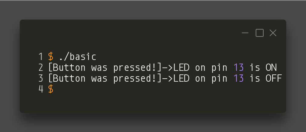
The output for this program looks like this (simulating a LED on the PC):
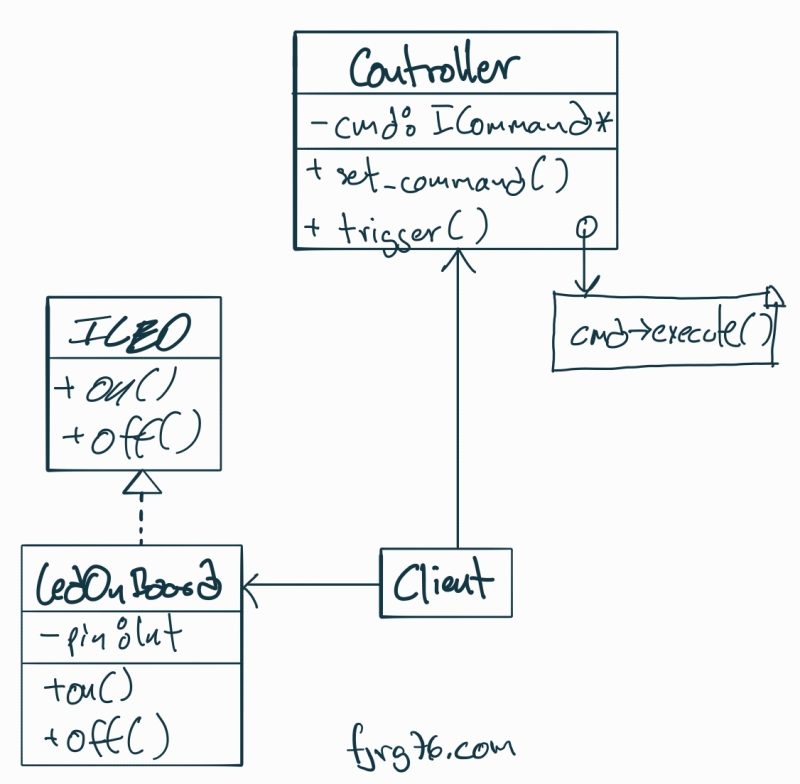
The UML diagram, from the client’s point of view, looks like:
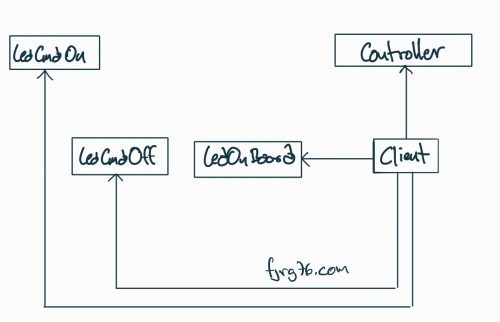
Note that at this point we are not interested in the details of the classes of the different actors involved, but simply in the relationships of creation and use. We will begin to examine those details below.
The Controller Class
The Controller class—also known as the Invoker—is in charge of issuing or triggering the commands. Unlike the Commands and the Receiver, the Controller class is not part of any hierarchy nor does it implement any interface. It is completely yours: you define it, adjust it, and name it according to your project’s needs.
This means its constructor, methods, and public API are totally flexible: they can receive additional parameters, handle their own state, or include system-specific logic.
class Controller
{
   private:
      ICommand* m_command{nullptr};

   public:
      Controller( ICommand* cmd = nullptr )
         : m_command{cmd}
      {}

      void set_command( ICommand* cmd )
      {
         m_command = cmd;
      }

      void press_button()
      {
         if( m_command )
         {
            std::cout << "[Button was pressed!]->";
            m_command->execute();
         }
      }
};
However, there are three elements that every Controller class must have, regardless of the project or implementation:
- (Line 4) A member variable of type
ICommand*(or equivalent reference) that stores the command to be executed. This is the bridge that connects the controller to the encapsulated action. - (Line 11) A method to change the command. This point is key: the Command Pattern shines precisely because it allows you to dynamically reassign which action should be executed.
- (Line 16) A method that triggers the command, meaning it invokes
execute()on the currently associated command. In our example, this method represents the «button press,» the trigger that activates the real action.
Additionally, I should clarify two details:
- It is not mandatory for the constructor to receive an initial command, but it is usually useful when you want the controller to have a defined behavior from the start. Plus, initializing our objects is a good programming practice.
- The text in line 20 is merely pedagogical to visualize what happens internally; in a real application, it could be omitted or replaced by a log.
With these pieces, we can already visualize the UML diagram where we stand in the pattern:
The Receiver Class
The Receiver class is the one that finally executes the action requested by the command. Unlike the Invoker, here a class hierarchy does exist, because we need a common contract that future implementations will have to fulfill. That contract is the ILED interface, which demands the on() and off() methods.
In this architecture, the Receiver is the expert in «doing» something real: turning on an LED, moving a motor, activating a relay, or whatever corresponds to your embedded project.
struct ILED
{
   virtual void on() = 0;
   virtual void off() = 0;
   virtual ~ILED() = default;
};

class LedOnBoard : public ILED
{
   private:
      uint8_t m_pin{0};

   public:
      LedOnBoard( uint8_t pin )
         : m_pin{pin}
      {}

      virtual void on() override
      {
         std::cout << "LED on pin " << (int)m_pin << " is ON\n";
      }

      virtual void off() override
      {
         std::cout << "LED on pin " << (int)m_pin << " is OFF\n";
      }
};
Let’s look at the key points:
ILED Interface
- Lines 1 to 6: We define the interface that forces any type of LED (physical, virtual, multiplexed, remote, etc.) to implement
on()andoff(). Although we are not going to use dynamic memory, we include a virtual destructor—a good practice when designing interfaces in C++—in case someone extends the pattern in a more complex way later on.
Concrete Class LedOnBoard
- Line 8: We create the concrete class that inherits from
ILED. By its name, we assume it controls a real LED connected directly to a microcontroller pin. However, the key point of the pattern is this: the command does not know nor care if the LED is real, virtual, simulated, or part of a pin expander. It only knows that it can callon()andoff()and that an LED will turn on or off, respectively. - Lines 10 to 16: We declare the internal variables of the LED (internal state) and its constructor. This part is not the pattern itself; it is simply what your hardware needs to initialize.
- Lines 18 to 26: We implement
on()andoff()with the appropriate code. In this example, I use virtual LEDs to facilitate the demonstration, but in real firmware, this is where the direct write to the GPIO register (or a call to the HAL functions) would go.
How is the UML diagram looking so far?
ILED interface
Why do we need an ILED interface and not simply create a loose LedOnBoard() function?
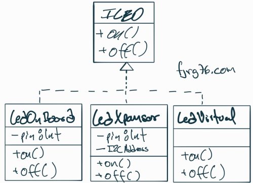
Because the interface will allow us to handle different «types» of LEDs:
- On-board: LEDs connected directly to a microcontroller pin.
- Expander: LEDs connected to a serial pin expander (PCF8574, HC595, etc.).
- Virtual: LEDs simulated on the PC (via calls to
printf()orstd::cout). - Remote: LEDs connected to another board and activated by a serial interface, such as RS232, RS485, CANBus, Ethernet, etc.
This idea is not reflected in this specific article because I wanted to keep the example simple, but in all cases, the classes must implement the on() and off() functions, making swapping LEDs much easier.
(Optional: If you want to know more about interchangeable components in embedded systems, I invite you to read this ARTICLE—but finish this one first!)
A UML diagram representing different types of LEDs looks like this:
Commands
Commands are the heart of the Command Pattern. This is where an action—turning on an LED, moving a motor, activating a relay—is encapsulated as an object, totally independent of who requests it and totally independent of who executes it.
struct ICommand
{
   virtual void execute() = 0;
   virtual ~ICommand() = default;
};

class Cmd_Led_On : public ICommand
{
   private:
      ILED* m_led;

   public:
      // el comando recibe al receptor:
      Cmd_Led_On( ILED* led )
         : m_led{led}
      {}

      virtual void execute() override
      {
         m_led->on();
      }
};

class Cmd_Led_Off : public ICommand
{
   private:
      ILED* m_led;

   public:
      // el comando recibe al receptor:
      Cmd_Led_Off( ILED* led )
         : m_led{led}
      {}

      virtual void execute() override
      {
         m_led->off();
      }
};
The ICommand Interface
- Lines 1 to 5: We define the interface for all commands. Traditionally the method is called
execute(), although the name is not mandatory; what matters is that all commands respond to the same message, regardless of what action they execute internally. We also include a virtual destructor for good programming practice, even though we won’t use dynamic memory here. Without this destructor, any command hierarchy would not be robust.
Concrete Command: Turn on an LED
- Lines 7 to 22: Here we define a concrete implementation of
ICommand. - Line 10: We declare a member variable
m_led, which stores a reference to the receiver. This is crucial: the command knows which receiver it will send the order to, but it does not know the emitter that activates it, nor does it know anything about the context where it is used. That independence is precisely what makes a command reusable across different scenarios, emitters, or architectures. - Lines 14 to 16: The constructor enforces receiving a valid receiver (that is, of type
ILED). For this example, we couldn’t receive a reference to motors or elephants. We know that any object implementing theILEDinterface will respond to the same messages, no surprises. - Lines 18 to 21: We implement
execute(). Here the real action happens: the command takes the abstract request and translates it into a call tom_led.on().
Concrete Command: Turn off an LED
Line 37: Note that the concrete action (off()) does not happen in the command, but in the receiver. The command only «triggers» the appropriate call. It doesn’t manipulate pins, doesn’t write to registers, and doesn’t know if the LED is real, virtual, or remote. Wow!
Lines 24 to 39: In the same way, we define a command to turn off the LED.
What is the profit of all this stuff?
A command is now an autonomous, portable, testable, reusable, and assignable object. The same command can be activated from different emitters (buttons, UART, WiFi, timers…), and the same emitter can execute different commands just by changing the reference.
This is where the power of the pattern really begins to be felt.
Source Code and Complete UML Diagram
You can download the complete code for this example from HERE. You might want to review it, part by part, along with the different stages of the UML diagram.
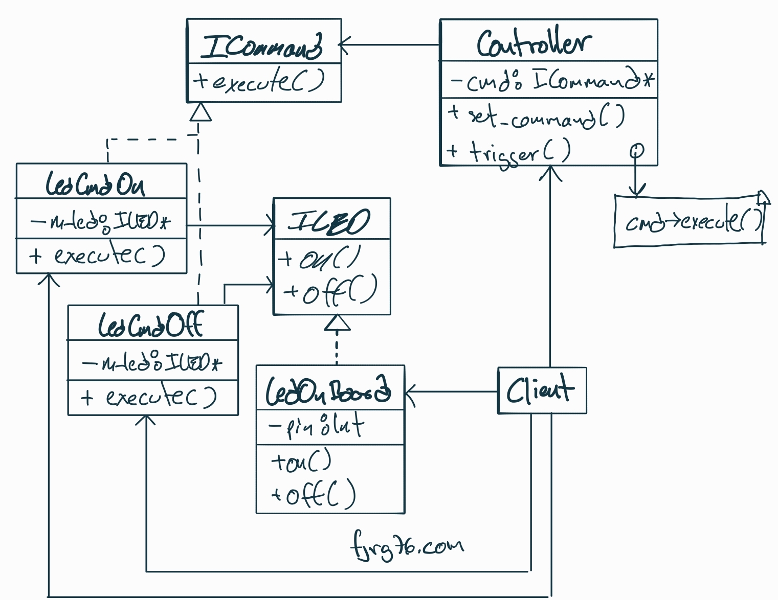
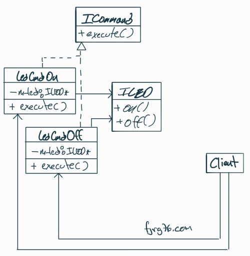
And speaking of the diagram, we can finally return to the complete diagram, with all its parts, and hopefully at this point it will seem less intimidating and more useful:

Before We Finish
As you have seen, the Command Software Design Pattern is not just an «elegant way» to encapsulate actions: it is a mental structure that helps you keep your programs organized, modular, and easy to extend. Perhaps you had already used it without calling it by its name—we all do—but knowing the pattern gives you a common language, a clear way to communicate your ideas, and a solid foundation for building more complex systems.
In this series, we will go step by step:
- First, the fundamentals (which we just covered).
- Then, composing commands to create macro-instructions.
- And finally, the always useful ability to Undo. If you work with robotics, HMI (Human-Machine Interfaces), or sequential action flows, I assure you this will be especially valuable.
If I see interest in this series, later on, we will explore more advanced variants:
- How to implement the pattern using static polymorphism with CRTP.
- How to leverage Modern C++ features to reduce code and maximize efficiency.
A final recommendation: adopt patterns as a tool to think about and structure your applications. Beyond the language and beyond the syntax, the real gain lies in how these schemes help you avoid fragile designs, separate responsibilities, and maintain uniformity across components:
- Commands always implement
execute(). - Receivers always expose the same interface.
- The
Controllerworks only with objects that fulfill the contract.
When your pieces fit together so precisely, your programs can grow without turning into a puzzle. And that, both in embedded development and desktop software, is worth more than Bitcoin.
See you in the next article. If you have questions, comments, or a use case where you have already implemented this, let me know!
Curso gratuito de FreeRTOS
Espero que esta entrada haya sido de tu interés. Si tienes dudas, preguntas o comentarios, déjamelos en la caja de comentarios. Si el artículo te sirvió de algo, podrías suscribirte a mi blog o compartir esta entrada con alguien que consideres que puede serle de ayuda también.
Apendix: Complete code just in case you don’t want to drive to Github
/* Copyright (C)
 *
 * This program is free software; you can redistribute it and/or
 * modify it under the terms of the GNU General Public License
 * as published by the Free Software Foundation; either version 2
 * of the License, or (at your option) any later version.
 *
 * This program is distributed in the hope that it will be useful,
 * but WITHOUT ANY WARRANTY; without even the implied warranty of
 * MERCHANTABILITY or FITNESS FOR A PARTICULAR PURPOSE.  See the
 * GNU General Public License for more details.
 *
 * You should have received a copy of the GNU General Public License
 * along with this program; if not, write to the Free Software
 * Foundation, Inc., 59 Temple Place - Suite 330, Boston, MA  02111-1307, USA.
 *
 * 2025 - fjrg76 dot com
 */

// basic

struct ICommand
{
   virtual void execute() = 0;
   virtual ~ICommand() = default;
};

// receiver (abstract):
struct ILED
{
   virtual void on() = 0;
   virtual void off() = 0;
   virtual ~ILED() = default;
};

class Cmd_Led_On : public ICommand
{
   private:
      ILED* m_led;

   public:
      // command takes the receiver:
      Cmd_Led_On( ILED* led )
         : m_led{led}
      {}

      virtual void execute() override
      {
         m_led->on();
      }
};

class Cmd_Led_Off : public ICommand
{
   private:
      ILED* m_led;

   public:
      // command takes the receiver:
      Cmd_Led_Off( ILED* led )
         : m_led{led}
      {}

      virtual void execute() override
      {
         m_led->off();
      }
};


#include <iostream>
class LedOnBoard : public ILED
{
   private:
      uint8_t m_pin{0};

   public:
      LedOnBoard( uint8_t pin )
         : m_pin{pin}
      {}

      virtual void on() override
      {
         std::cout << "LED on pin " << (int)m_pin << " is ON\n";
      }

      virtual void off() override
      {
         std::cout << "LED on pin " << (int)m_pin << " is OFF\n";
      }
};


class Controller
{
   private:
      ICommand* m_command{nullptr};

   public:
      Controller( ICommand* cmd = nullptr )
         : m_command{cmd}
      {}

      void set_command( ICommand* cmd )
      {
         m_command = cmd;
      }

      void press_button()
      {
         if( m_command )
         {
            std::cout << "[Button was pressed!]->";
            m_command->execute();
         }
      }
};


int main()
{
   // create the commands receiver:
   LedOnBoard led_on_board{ 13 };

   // create the commands:
   Cmd_Led_On  cmd_led_on{  &led_on_board };
   Cmd_Led_Off cmd_led_off{ &led_on_board };

   // create the controller and pass the initial command:
   Controller button_A{ &cmd_led_on };

   // press button A and command cmd_led_on will fire:
   button_A.press_button();

   // assign a new command to button A:
   button_A.set_command( &cmd_led_off );

   // press button A and command cmd_led_off will fire:
   button_A.press_button();
}

Mi perfil completo lo puede encontrar en: https://www.linkedin.com/in/fjrg76-dot-com/
- Writing Scalable Firmware: Implementing the Command Pattern in C++ - diciembre 4, 2025
- Patrón de diseño de software Command para sistemas embebidos para los no iniciados - noviembre 30, 2025
- Breathe Life into Your Displays with the Arduino Print Class - marzo 17, 2025
Deja una respuesta
Lo siento, debes estar conectado para publicar un comentario.