A Beginner’s Step-by-step Guide to Custom Power Symbols in KiCAD
Tired of generic power symbols that don’t communicate function or add personality to your schematics?
Ever struggle to find the perfect power symbol for your unique project in KiCAD’s default library?
Unlock the power of custom symbols! Imagine a schematic with a CR2032 coin cell powering a low-power sensor and a 7.4V LiPo pack driving a high-power motor. KiCAD’s default symbols just won’t cut it! The good news? Creating custom symbols is easier than you think!
This small step-by-step guide will walk you through the surprisingly easy process of creating custom power symbols that perfectly reflect your project’s needs, injecting personality into your schematics and boosting clarity like never before.
Get ready to craft unique power symbols that elevate your KiCAD schematics to a whole new level!
1.
From the main KiCAD’s window open the Symbol editor:

2.
- Right click in a library of your own in the left tool bar, or
- (Optional) Create a new library: File -> New library. In either case choose New symbol.
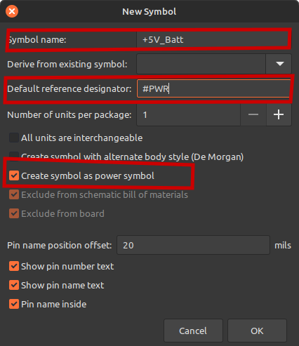
3.
- For the Symbol name pick a unique name that resembles your power symbol, for example: +5V_Batt. Choose the name carefully: you’ll need it later on.
- The «Default reference designator» field must always be #PWR for power symbols, and also check the select box named «Create symbol as power symbol».
- Press the «Ok» button to finish.
4.
Back in the main window press letter P (or p) in order to insert a pin. Every power symbol is build upon a single, invisible, pin. You can also clik on the icon:

that is located in the right tool bar.
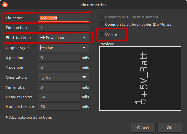
- For the pin’s name choose the same as the one in step 3: +5V_Batt
- For the Pin number choose 1
- For the «Electrical type» field choose «Power input«.
- For the Orientation field choose «Up».
- For the Pin lenght field choose 0.
- Make sure to uncheck the «Visible» property check box; the pin must be invisible.
- Press the «Ok» button to finish.
5.
- Back in the main window align the pin to the 0,0 coordinates (that small white circle in the picture above should be centered).
- Now draw your custom power symbol using the graphical tools: lines, arcs, circles, etc.
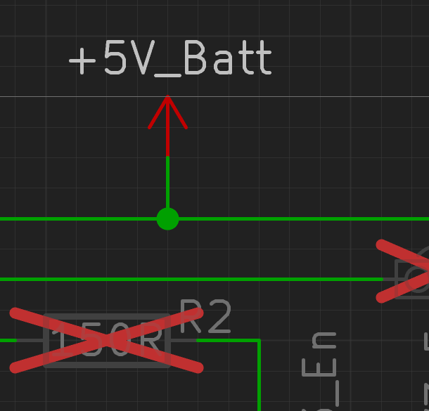
- Your power symbol should look like:
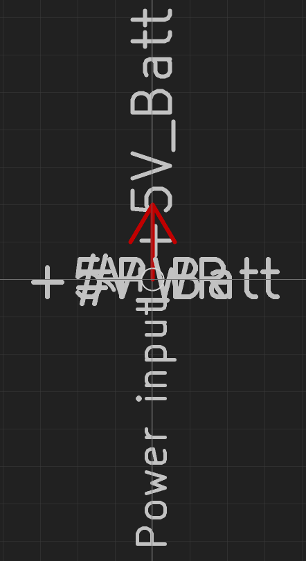
Don’t worry for all that cumbersome texts, they won’t appear in your schematics, just pay attention to that small white circle that must be centered (at coordinates: 0,0). This example used only graphic lines (the ones in red color), but you can use arcs and circles as well.
TIP: If you want your symbol to match graphically those from KiCAD you need to choose a 5 mils grid. Using this grid’s size my symbol mimics perfectly the KiCAD’s positive power symbols (+5V, +3.3V, etc):
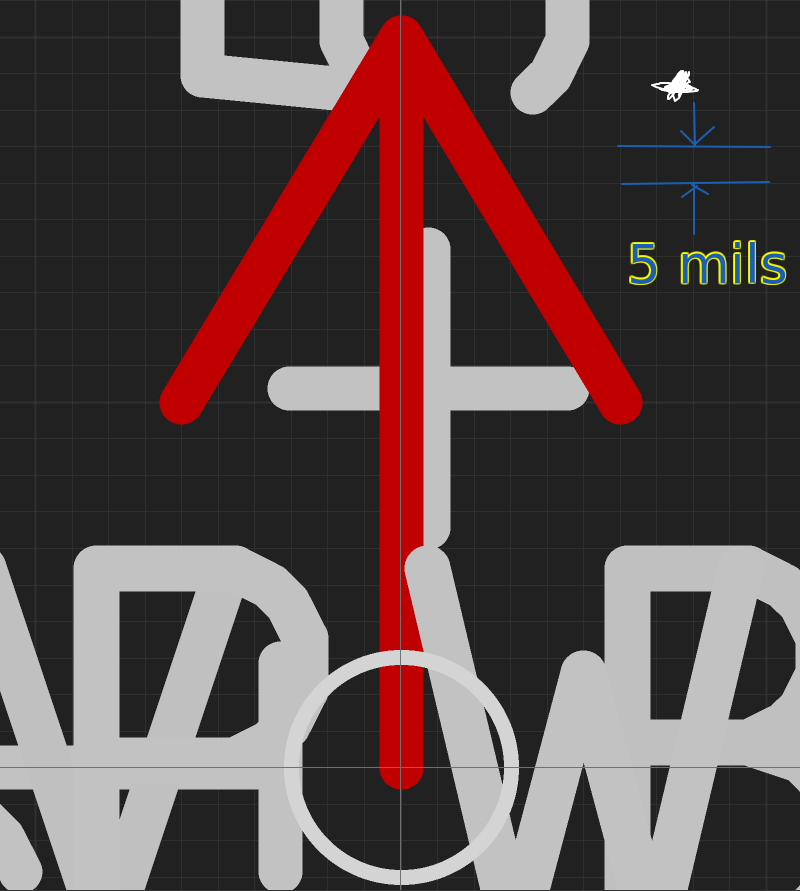
For the sake of completeness, this symbol is 100 mils tall and 60 mils wide; arrow is 50 mils tall.
6.
When you consider that your symbol is graphically ready, look for this icon in the upper tool bar and click it:

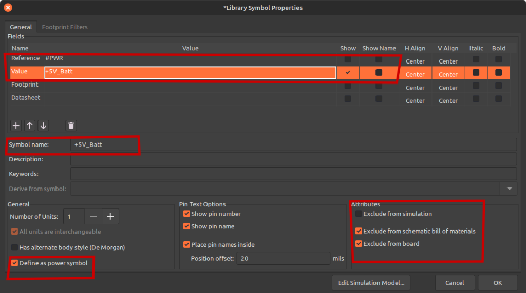
The window Library Symbol Properties will show up.
- The «Reference» field should contain the #PWR string, and unselect its Show box property.
- For the «Value» field choose the same name as the symbol; in this example: +5V_Batt. Make sure the «Show» box for this field is selected. The Symbol name field text and the Value field text MUST match.
- If you’re feeling a compelling reason to add some description for your new awesome power symbol, you can do it in the field «Description».
- Your power symbol neither have Footprint nor Datasheet attributes.
- Speaking of attributes look for the section with this name and make sure that «Exclude from schematic bill of materials» and «Exclude from board» options are both selected. You can’t order a power symbol from mouser.com or digi-key.com, can you?
- Press the «Ok» button and save your new symbol: File -> Save (or Ctrl-s)
7.
Now you can test your new symbol in your schematics. In case there’s a schematic document already opened, look for this icon and click on it:

It will take you to your schematic. You should now see your awesome power symbol. Use it wherever is appropriate:
If you don’t like how it looks like, return to the Symbol editor and make the necessary graphical changes and repeat until you’re happy.
8.
Once you’re happy with your power symbol you can use it as any other power symbol: in the schematics editor press the letter P (or p) and look for your symbol, either typing +5V_Batt in the search text field, or with the mouse in the bottom panel, and then double click on its name (or select it and press the Ok button):
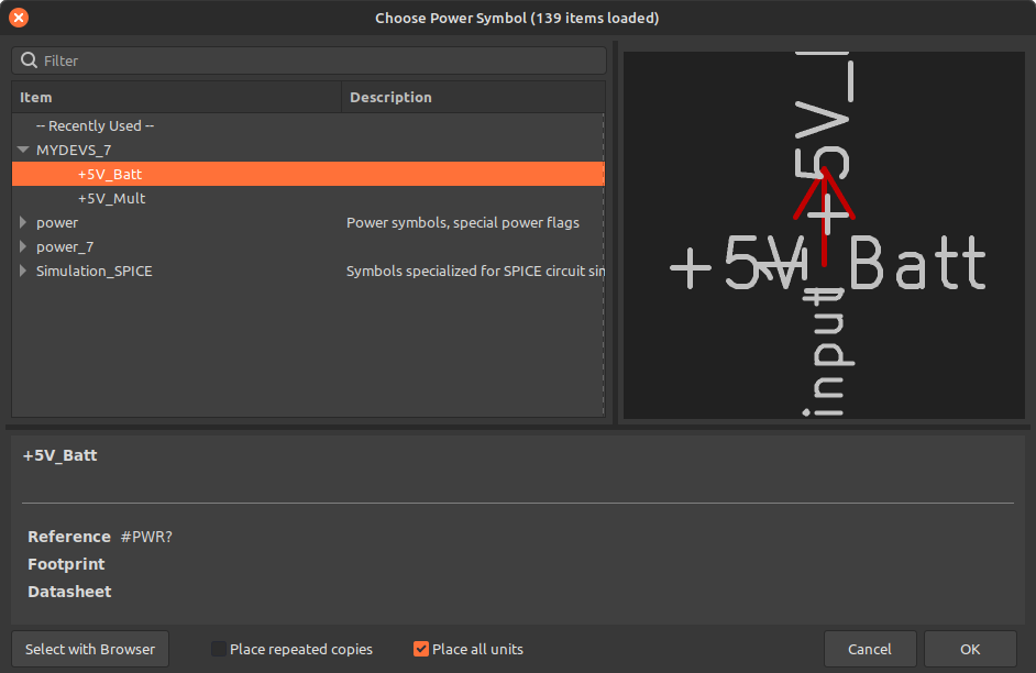
Congratulations, you’ve just created your first KiCAD’s power symbol, cheers!
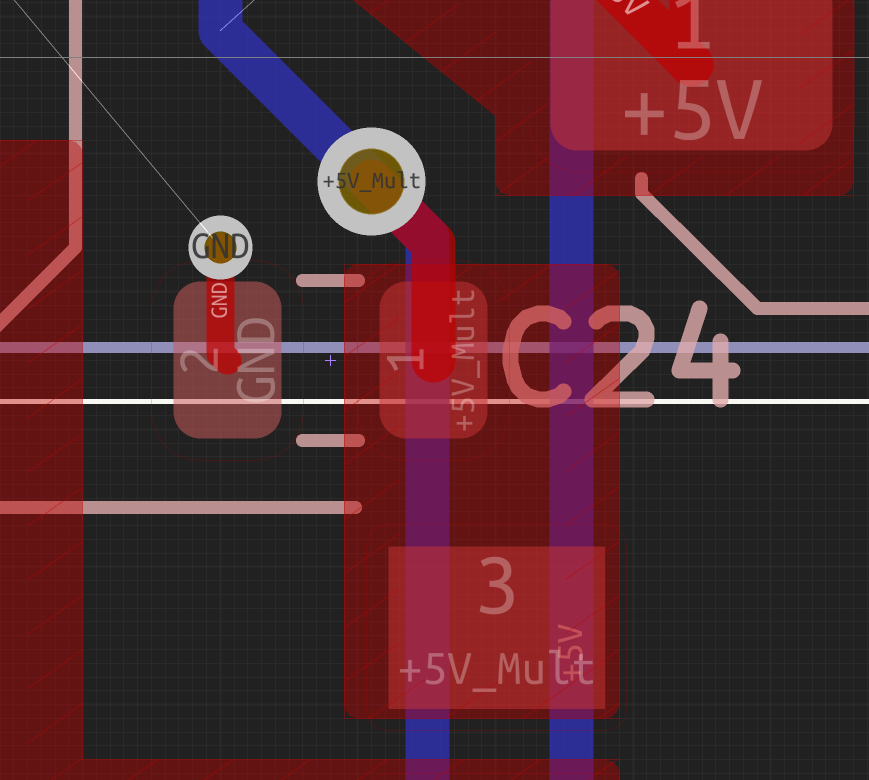
TIP: Power symbols have global scope, which means that in a hierarchical schematic the power symbols are «seen» in all project’s pages.
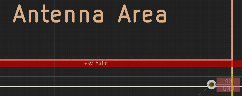
TIP: Open the PCB editor and make sure that the net +5V_Batt (for our example) is shown in their corresponding tracks. These next pictures com from an ongoing project in which I’ve created a power symbol +5V_Mult (that in turns forced me to investigate how to create power symbols and compelled me to write this tutorial for you and myself from the future), but your result must be similar:
Did you imagine this process was that easy? Me neither!
Have comments or questions? Please let me know them in the comments box below. Don’t worry if you see text in spanish, I also speak english, as you’ve just read.
Comment and share for more KiCAD’s tips and tricks, I have dozens! However, I don’t know in which are you interested in.
Source: https://klc.kicad.org/symbol/s7/s7.1/ (it’s not as good as my tutorial)

Mi perfil completo lo puede encontrar en: https://www.linkedin.com/in/fjrg76-dot-com/
- Arduino and ESP32 whims - diciembre 17, 2025
- Writing Scalable Firmware: Implementing the Command Pattern in C++ - diciembre 4, 2025
- Patrón de diseño de software Command para sistemas embebidos para los no iniciados - noviembre 30, 2025
Deja una respuesta
Lo siento, debes estar conectado para publicar un comentario.