Cold starting might damage your electronic circuits, but here’s a way to protect them
(Para español da click aquí.)
Have you noticed those sparks when you plug in your charger or adapter to the mains?

This phenomena is due to the discharged power supply input capacitors; in this state they behave as short circuit.
This short circuit can spread to your electronic circuits, reducing their useful life or other circuits that could be connected to them.
In my laboratory I have a power supply and an oscilloscope that when I connect them to electrical power they wait a certain time before going into active mode.
Both are quite expensive and delicate devices and for the same reason their designers have taken care of the phenomenon of cold start (that is, when the capacitors of their power supply are discharged).
The power supply waits two seconds before turning on voltage to my circuits after I pressed the power button, and the oscilloscope does the same by waiting around that same time to start working.
Have you heard those «clicks» inside devices like the ones I mentioned? Well, it is nothing other than the start delay circuit, and it is the one that protects both them and the circuits that we connect them from cold start.
This circuit, delay start circuit, seems to be quite a complex and expensive circuit, but it is not! Keep reading so you know how to build yours with components you already have in your laboratory or workshop, including the famous 555!
On-delay timer
The principle of operation is simple: wait an amount of time after we connect the starter to electrical power for it to enable the voltage to the circuit we want to protect.
In industrial automation, this circuit is called on-delay timer.
An on-delay timer has a trigger input and a contact that activates when the programmed time has expired from activation on the trigger input.
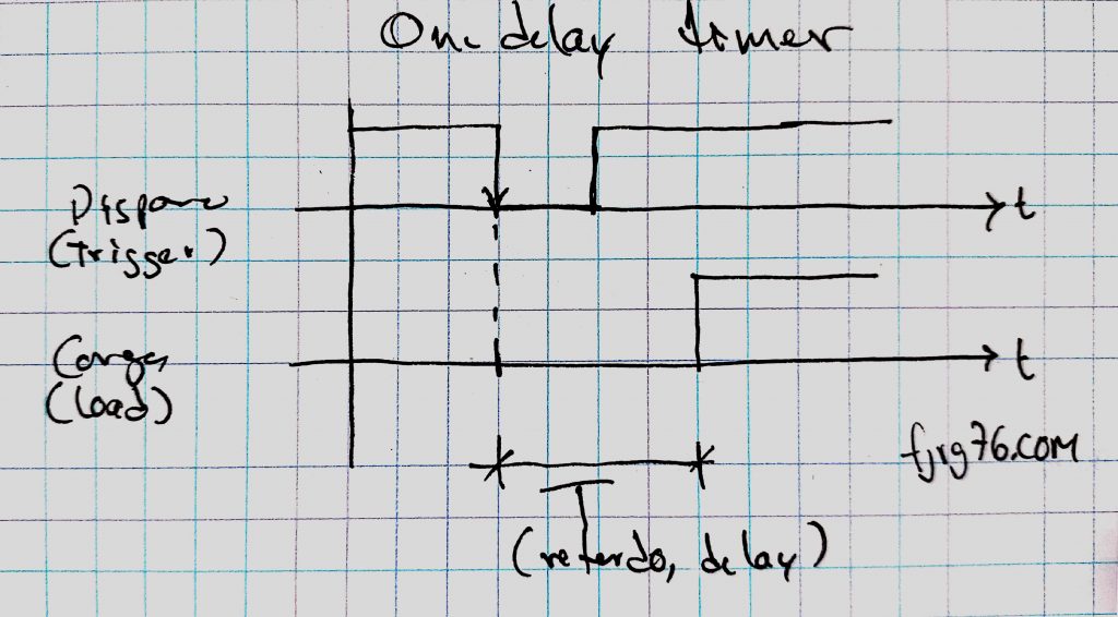
With this configuration, one circuit triggers the time and another circuit is enabled when the time has expired.
Our solution is based on this principle, but with two slight modifications.
On-delay starter
Here the idea is that the trigger signal is activated at the precise moment in which we connect the starter to the main power supply; that is, there will not be an external trigger circuit, but it will be integrated into the starter itself.
On the other hand, the voltage that the circuit under protection will receive will be the same as that of the input. That is, while in a common on-delay timer the trigger signal can be a 5V pulse and the load may be some monster of 220V and 100A, in our circuit if the input voltage is 12VDC, then the output voltage will also be 12VDC and the current will be limited by the size of the output relay.
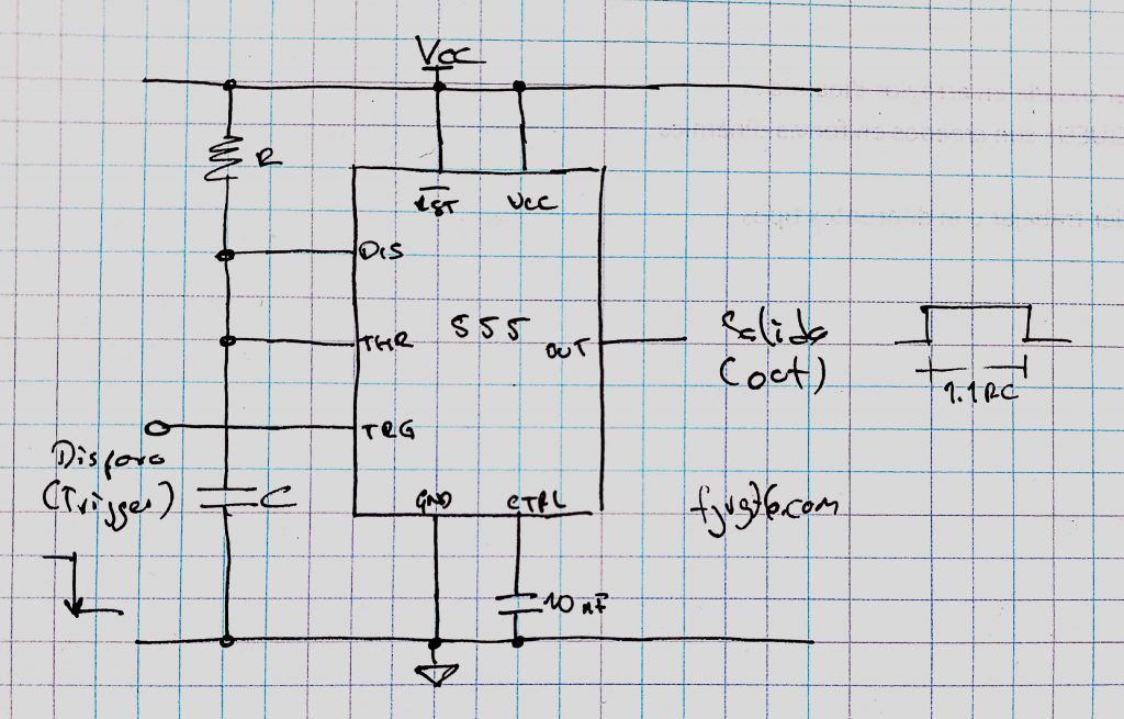
The heart of the circuit is a 555 configured in monostable mode, that is, an input pulse generates an output pulse.
However, we must take into account some considerations, because as I have already said, the negative start pulse (from high to low) must be given automatically when the starter is energized; that is, we will not have a trigger button or switch, as in classic circuits.
Circuit
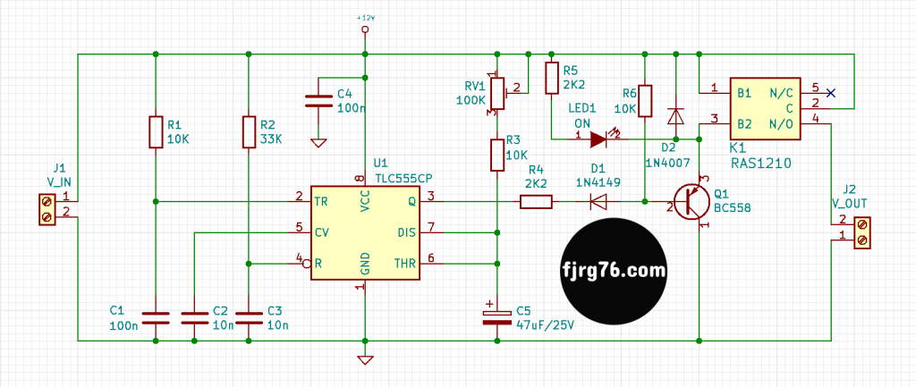
To achieve this I had to add two more RC networks: R1 / C1 in the trigger signal (pin 2), and R2 / C3 in the reset terminal (pin 4). For delays of 0.5 seconds or more you should not change these values.
RV1 / R3 / C5 is the main RC network which sets the delay at startup (on pins 6 and 7). The delay time is obtained with the expression: t = 1.1 * R * C, where R is in Ohms, C in Farads and t is in seconds.
For example, if RV1 + R3 = 100KOhms and C5 = 47uF, then the delay time is 5.17 seconds.
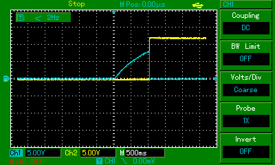
In my prototype I have RV1 + R3 = 19.2KOhms, with which the theoretical delay is: 1.1 * (19.2K) * (47u) = 0.996 seconds. This value is very close to the one I measured:
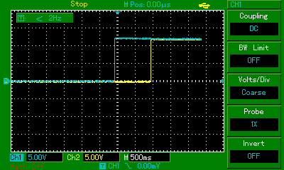
In the following image we can see the charge of the capacitor C5 when we apply voltage to the circuit. When it reaches 9V (which is 2/3 of 12V) the output of 555 (pin 3) is activated:
And speaking of the output terminal, pin 3, notice that I used a PNP transistor for Q1. This is so because what we want is for the output to stay low while the time elapses, and once the output has elapsed, it goes high.
Basically what the PNP transistor does is to invert the 555’s output signal. In a normal monostable circuit the output goes high as time passes, but we want the opposite, hence the need to reverse the polarity.
Diode D1 is there to ensure that Q1 turns on only when the 555’s output is low. R1 biases Q1 in its non-active zone for the same reason.
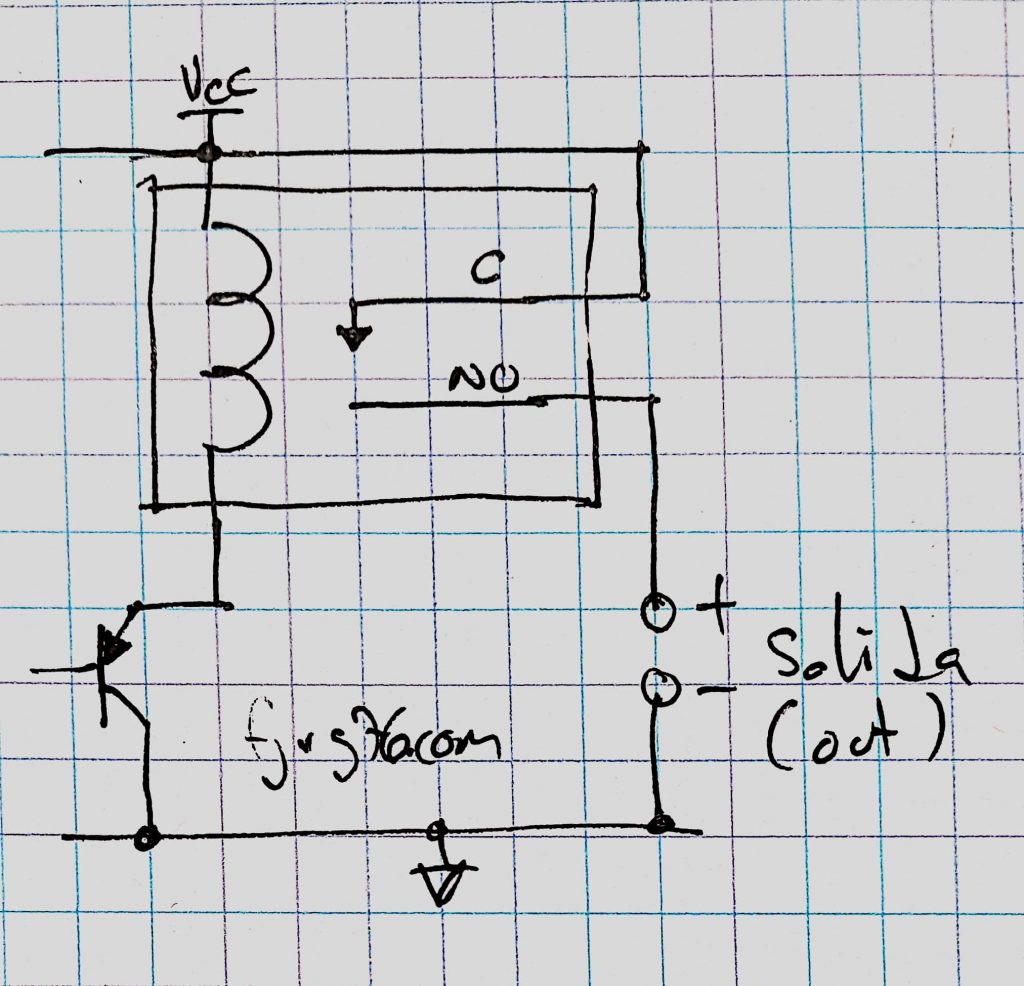
Finally we have the output relay, K1. Note that its Common terminal (pin 2) is connected to 12V itself. That is, the common receives 12V and when the time has elapsed and Q1 energizes its coil (pin 3), then the normally open contact (pin 4) makes contact with the 12V input and delivers it to the load.
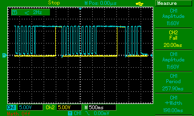
In the following image we can see the behavior of the circuit when the input voltage is unstable. This is the second reason why I designed and built this circuit:
Prototypes
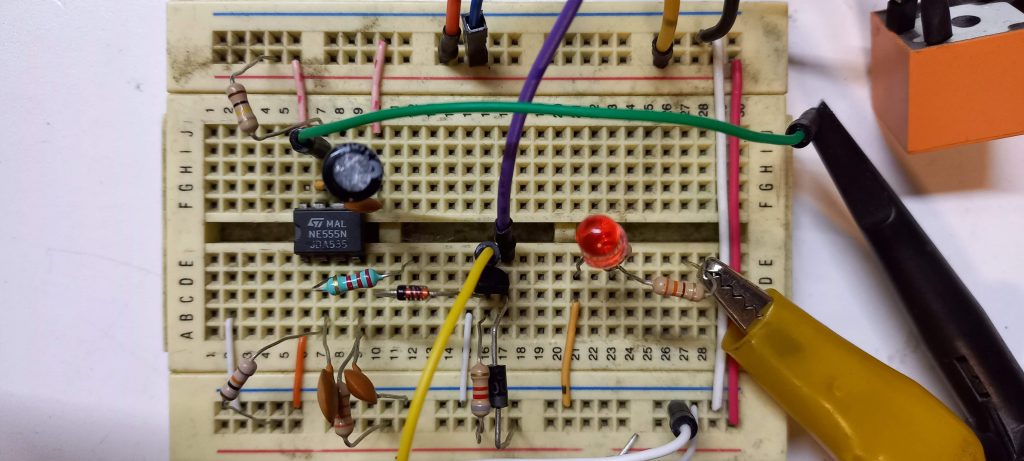
In the following image you can see the first prototype on a prototype board:
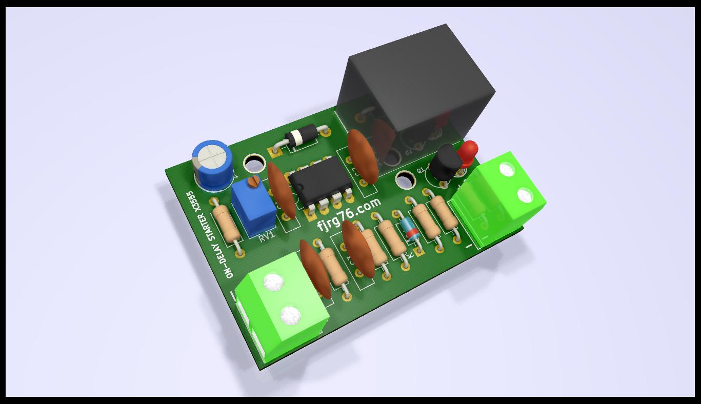
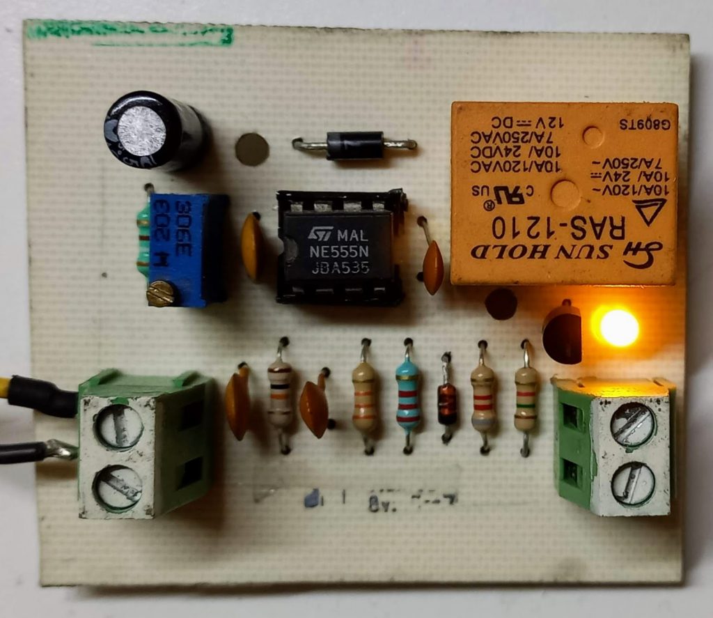
And in this image the same circuit but already on a homemade printed circuit:
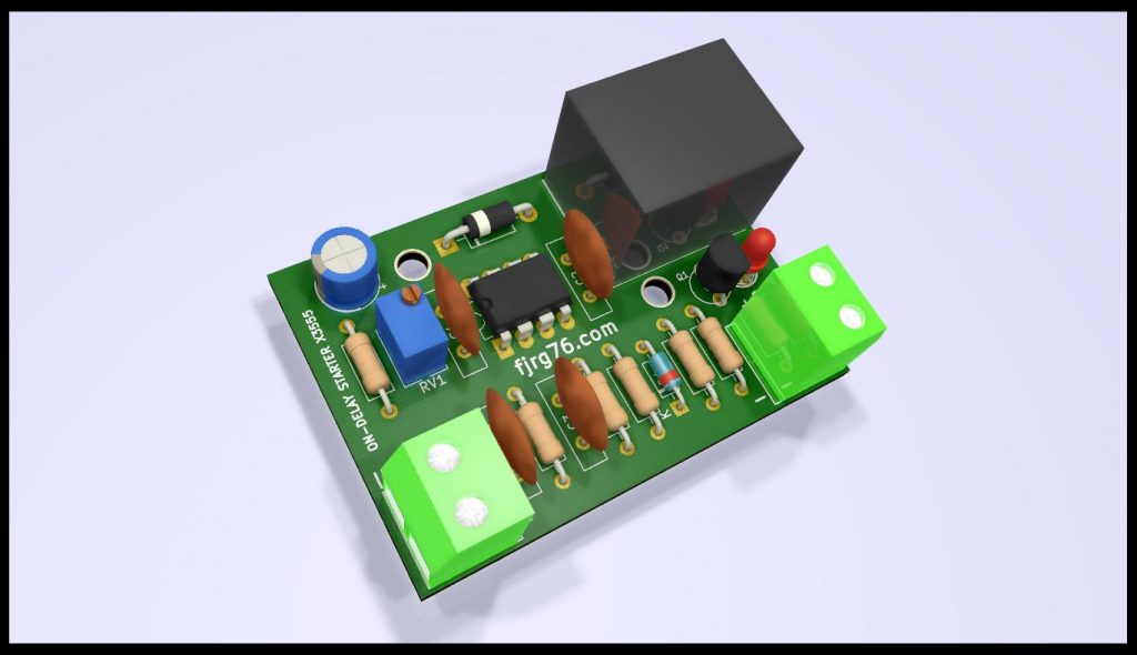
And here is what the artist imagined (when I have them professionally made this is what they will look like):
What’s next?
- You can modify the working voltage of the circuit by changing the voltage of the relay. It should work from 5 to 15V without major inconvenience. If you do, calculate a value for R5 in such a way that the LED reaches about 5 milli amperes. It may also be necessary to modify R4 to ensure correct bias of Q1.
- You can modify the delay times by changing RV1, R3 and C5. My recommendation here is that you keep the value of C5 as low as possible, and if necessary, increase that of RV1. A very large value for C5 will cause it to take a long time to discharge, which means that this starter will not be able to protect you when the input voltage is connected and disconnected very quickly.
- The width of the power rail tracks (VCC and GND) must be in accordance with the current that the circuit must provide.
- Subscribe to my blog!
You can get the PCB in PDF format of this design for a couple of bucks so you can build it yourself with home-made tools and techniques. You’ll we redirected to an e-store so you feel confident on your purchase.
Do you already know my free course on Arduino in real time, using the Arduino UNO or the Arduino Due and FreeRTOS (in spanish by now)?
Would you like to be one of the first to receive updates to my blog? Subscribe, it’s free!

Mi perfil completo lo puede encontrar en: https://www.linkedin.com/in/fjrg76-dot-com/
- Arduino and ESP32 whims - diciembre 17, 2025
- Writing Scalable Firmware: Implementing the Command Pattern in C++ - diciembre 4, 2025
- Patrón de diseño de software Command para sistemas embebidos para los no iniciados - noviembre 30, 2025
2 COMENTARIOS