Wash your hands, save water and avoid Covid-19 with this automatic water dispensing circuit based on the 555
(Para leer este artículo en español da click aquí.)
Introduction
It has always been important to wash your hands as often as possible to avoid any number of illnesses. And as of 2019 the situation became delicate due to the Covid-19 virus. Experts on the subject have recommended that we wash our hands whenever we return from the street or after being in contact with a possible source of the virus to reduce the probability of contagion.
But on the other hand, one danger of washing our hands, whether in our bathroom or in a public place, is that the utensils and accessories could be contaminated with bacteria or viruses, by the many people who used it before us.
The circuit I’m going to describe below will prevent from touching the water faucets every time you or your family members use the toilets, reducing the possibility of getting infected if someone brought the virus to your home.
The circuit is simple, compact, cheap, and easy to build; it is based on the the famous 555 in monostable mode, infrared light and an analog comparator.
A nice secondary effect of this circuit is that it will also help us save a lot of water.
¿De qué trata?
What is it about?
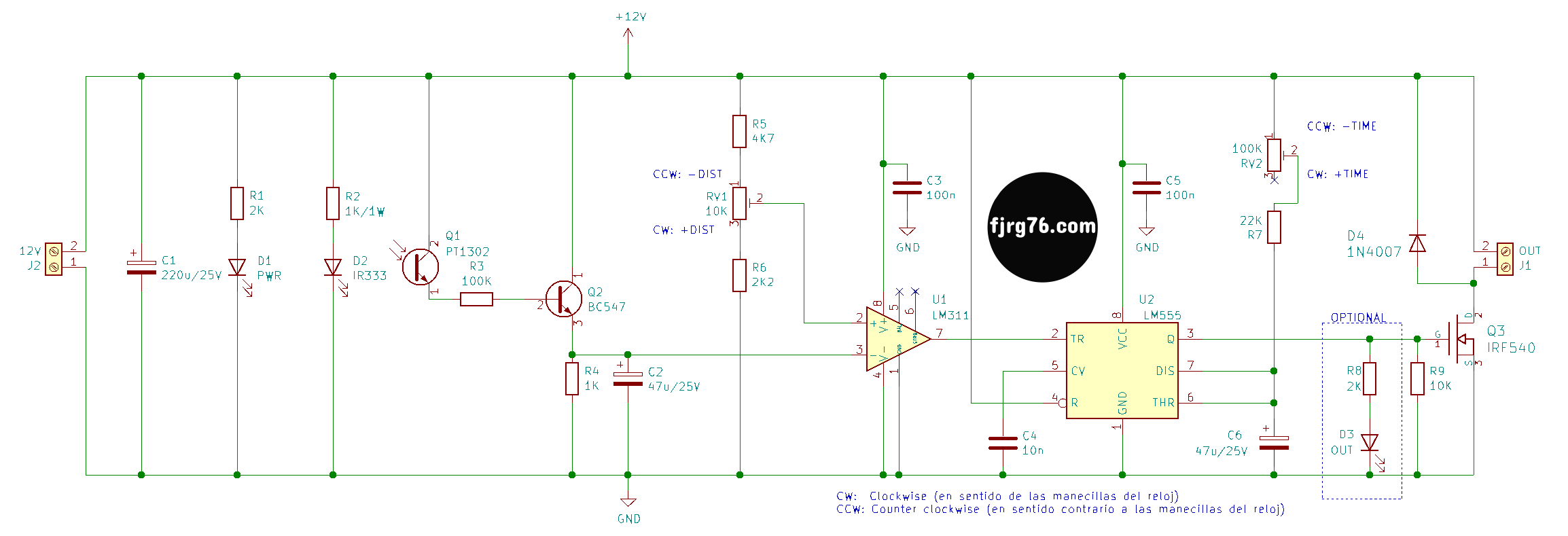
The circuit emits infrared light, and when we bring one of our hands closer, the light reflects back to a detector. The output of this detector enters into analog comparator, which is responsible for triggering the next stage. This comparator also allows you to adjust the detection distance in the range of a few centimeters. The stage that triggers the comparator is the 555 circuit in monostable mode, or single pulse generator. Once the monostable is triggered, it will activate a solenoid valve (via a MOSFET transistor) for a few seconds. This valve is responsible for letting the water pass or block it. The activation time is also adjustable in the range of a few seconds.
Playing with the values of different components you will be able to obtain greater or lesser ranges for the detection distance and the activation time.
Circuit
Etapa de transmisión y detección de la luz infrarroja (IR)
The transmitter is an IR LED that emits infrared light continuously, while the receiver is a photo-transistor, also in the infrared spectrum. The current flow in the photo-transistor is proportional to the incidence of the reflected IR light from the emitting LED and our hand.
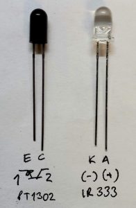
However, our hands do not act as a mirror, on the contrary, they will absorb much of the IR light from the transmitter, so the portion of light reflected by our hand will be minimal, and therefore, the current in the photo-transistor will be small. That’s why we need a transistor that will amplify that small current to levels that can be used by the comparator of the next stage. This transistor is also very common, the BC547, and any equivalent will work. The important thing is that it should be a low power BJT (Bipolar Junction Transistor) and not a FET, Field Effect Transistor (like the 2N7000).
The current amplified by the BC547 transistor is converted to voltage by resistor R4, since the comparator uses voltages and not currents: the more photons reflected, the higher the voltage on R4.
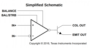
Comparator
The comparator is another very common chip, the LM311. When the voltage at pin 3 (-) is less than the voltage at pin 2 (+) the output signal at pin 7 is held low. When the voltage at pin 3 exceeds the voltage at pin 2, then the output signal at pin 7 goes high, and will stay high for as long as the condition lasts.
Continuing with our circuit, the output voltage of the BC547 is connected to the (-) input of the comparator. The (+) input is connected to a variable voltage, which is what establishes the trigger threshold. When the voltage of the BC547 exceeds this threshold, the comparator output goes to high level, and it will stay that way as long as our hand is in front of the IR LED. The comparator’s output is connected to pin 2 (Trigger, TR) of the 555 chip (which is been configured in monostable mode).
Resistors R5, R6, and RV1 set a window for the sensing distance. The values are not critical and you can adapt them to your needs; you could even set R5 to 0 (zero) Ohms, without seriously affecting the circuit’s performance.
With the given values, the detection range is between 2cm (RV1 turned fully to the left) and 8cm (RV1 turned fully to the right).
555 in monostable mode ( or one-shot)
The positive pulse* received on pin 2 of the 555 (Trigger, TR) deactivates the transistor internal to the 555 connected to pin 7 (Discharge, DIS) allowing capacitor C6 to start charging. At the same time the positive pulse causes that pin 3 (Q), which is the output of the 555, to go high.
* A positive pulse is when the voltage goes from a value equal to or less than 1/3 of VCC (4V in our 12V circuit) to a value greater than or equal to 2/3 of VCC (8V in our circuit).
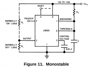
C6 is also connected to the pin 6 (Threshold, THR) which detects when the voltage on the capacitor has reached 2/3 of VCC. When this happens then the signal at pin 3 goes low and the internal transistor at pin 7 turns on to discharge the capacitor.
The equation to calculate the time that the signal on pin 3 will remain active (high) is:
t = 1.1*(R7+RV2)*C6
The resistors are in Ohms, the capacitance in Farads, and the time in seconds. R7 is fixed to have a minimum activation time.
| C6 | R7 | RV2 | Tiempo [s] |
| 47uF | 22K | 0K (CCW: far left) | 1.13 |
| 47uF | 22K | 100K (CW: far right) | 6.13 |
As you may have noticed, these values are not critical and you can adjust them to your needs.
TIP: For very long times keep the value for C6 low and increase R7 and RV2 as much as possible (a safe value for R7 is a tenth of RV2).
Etapa de potencia
The solenoid valve I used for this circuit has a current consumption of 500mA at 12VDC, but pin 3 of the 555 is not capable of delivering it, so we require a power circuit.
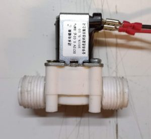
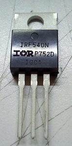
Here we have two options: to use a relay, or to use a MOSFET transistor. I opted for the latter with the IRF540 MOSFET transistor (or equivalent).
A MOSFET transistor, for this application, has several advantages over a relay:
- It is less bulky, which means using a smaller case,
- It is cheaper,
- It does not generate heat,
- And the most important feature: being an electronic component, it has no mechanical parts , so it will last much longer.
NOTE: If you use this circuit with solenoid valves that draw more current, then you should consider adding a heat sink to the MOSFET; and in extreme cases you may have to change it to a relay (for example, if the solenoid valve has a 127VAC winding, or if the solenoid valve uses a motor as an actuating element).
The low heating property of the IRF540 is due to the fact that the internal resistance between its terminals D (Drain) and G (Gate), known as R(DSon), is only 0.044 Ohms. If we do the math we get:
P=RI^2
P=(0.044Ohms)(500mA)^2
P=11mW ó 0.011W
This small power value, added to the transistor’s TO-220 case, made it the perfect option for this application.
By the way, also note that I used a freewheel diode to return the back electromotive force (back EFM) generated by the collapse of the magnetic field of the solenoid valve winding when the voltage is removed. (All coils generate a back EMF when power is removed, so relays always include a diode in this configuration as well.)
Without this diode the back EMF (which is high value and short duration) would try to go through the MOSFET, possibly damaging it in the medium term.
I normally use the 1N4007 for this purpose, but a signal diode, like the 1N4147, would also work.
Prototypes
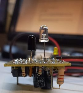
My first home-made prototype of this circuit looks like:
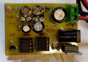
In this first version I placed the transmitter and receiver on cupper layer due to the case that I was using for the first tests. Likewise, for the variable distance and time control resistors I used a couple of trimpots, since these are very cheap they are very easily available in my country (México).
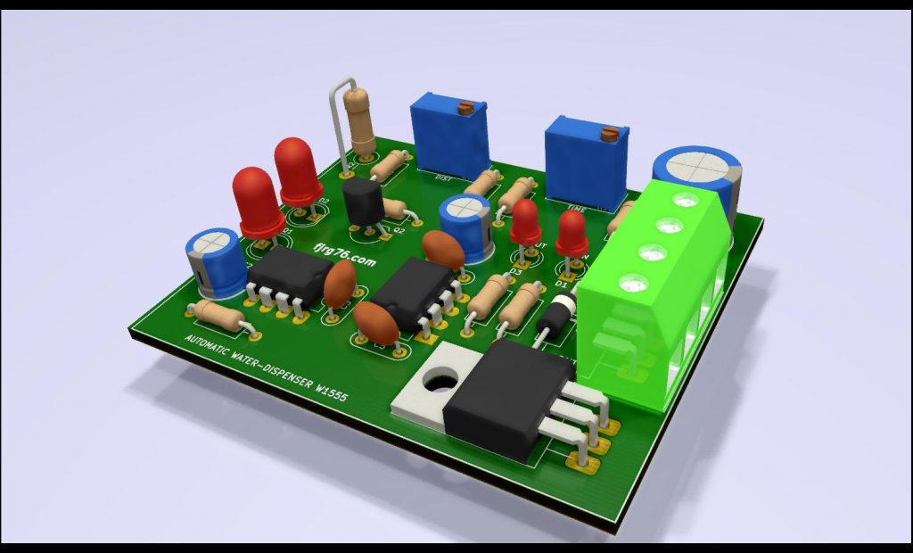
However, for the final version I made three changes, two precisely in the mentioned components:
- I placed the transmitter and receiver on the components layer.
- I used the classic blue potentiometers that we see on the Chinese boards. The idea is that electronics enthusiasts from other countries can also build it.
- I changed the power connector, I put a screw-connector on it because I think it is more comfortable for permanent installations.
- I made the tracks, which are on the cupper layer, thicker so you don’t have problems making the PCB with homemade techniques.
Having said that the artist’s vision looks like this:
Mounting Tips
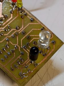
It is important that diode D2 and phototransistor Q1 are slightly angled towards each other. The exact angle is not critical, as long as our hand in front of Q1 reflects as much ligth as possible.
It is also very important that D2 is a little bit above Q1 to prevent the latter from capturing infrared light when there is no object in front of it.
If you don’t have space in your case for the different heights, then you could put a small light barrier between both components, for example, a piece of black cardboard or a piece of PVC card (of the credit card kind).
Whats Next?
You could build this circuit on a breadboard or you can design your own PCB and start saving water every time someone in your house washes their hands.
You could also use this circuit in the kitchen sink, or for a semi-automatic irrigation, or for as general-purpose timer (using as a trigger to put an object in front of Q2 ), or wherever you can think of!
Fiverr LinkedIn YouTube Instagram Facebook
You can get the PCB in PDF format of this design for a couple of bucks so you can build it yourself with home-made tools and techniques. You’ll we redirected to an e-store so you feel confident on your purchase.
Subscribe to my blog!

Mi perfil completo lo puede encontrar en: https://www.linkedin.com/in/fjrg76-dot-com/
- Arduino and ESP32 whims - diciembre 17, 2025
- Writing Scalable Firmware: Implementing the Command Pattern in C++ - diciembre 4, 2025
- Patrón de diseño de software Command para sistemas embebidos para los no iniciados - noviembre 30, 2025
1 COMENTARIO