4 digits, 7 segment display module using the 74HC595 shift register chip
(Lee este artículo en español aquí.)
Introduction
A very required hardware in our projects is the display module. And we have many types of them, from the traditional 7-segment LED to OLED microdisplays, through 16×2 LCDs and graphics. Each one has its pros and cons, and which one we use will depend entirely on the project we’re working on.
In this article I want to show you how to use a 7-segment LED display using the 74HC595 chip to control the segments and MOSFET transistors to control the digits.
Hardware
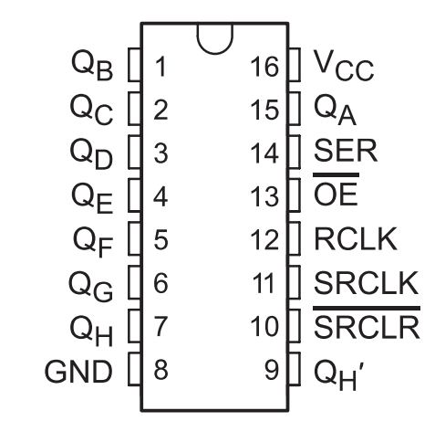
The 74HC595 chip is a shift register that allows us to reduce the number of pins, from 8 to 3 (and maybe 4), to control the 8 segments of a single 7 segment LED digit. We are going to need the 3-line SPI serial communications protocol (although we are only going to use 2) that is present in practically all microcontrollers on the market.
Another advantage of using the HC595 is that it serves as a current amplifier for each segment; remember that ultimately each of these is an LED, and thus we protect the microcontroller from current overloading.
As I mentioned, the digits will be controlled with discrete MOSFET 2N7000 transistors, although it is also possible to use BJT transistors (bipolar junction transistors, such as BC547, BC337, etc). And we could also use encapsulated transistors (like the ULN2003), but 4 discrete transistors is a better option for a 4-digit display, like the one I’m going to show to you.
Using MOSFETs instead of TBJs has the advantage that we do not need the base resistor of the latter, and thus we save on components and space on the printed circuit board.
Diagram
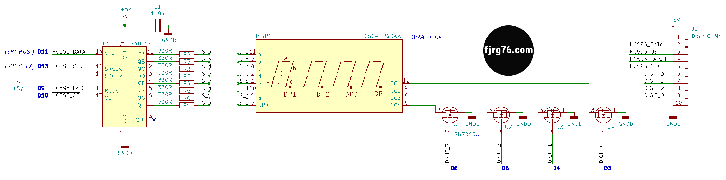
The texts in blue are the Arduino lines that I’ve used, but you can vary some of them if required, except D11 and D13, since these are the pins corresponding to the SPI signals SCLK (clock signal, serial clock) and MOSI (data signal from the micro to the chip, master out, slave in). In the diagram they are the pins 11 (SRCLK) and 14 (SER) of the HC595, respectively.
Note that I’ve used labels instead of «wires» to connect the HC595 to the display. This gives us a lot of flexibility. When I built my first prototype on a breadboard I used a 1 to 1 map: QA output to segment a, QB output to segment b, etc. This worked very well there, but to design a one layer PCB became a nightmare (which I had already anticipated). When I started designing the printed circuit I changed the map in such a way that the tracing did not involve using jumpers, or as few as possible.
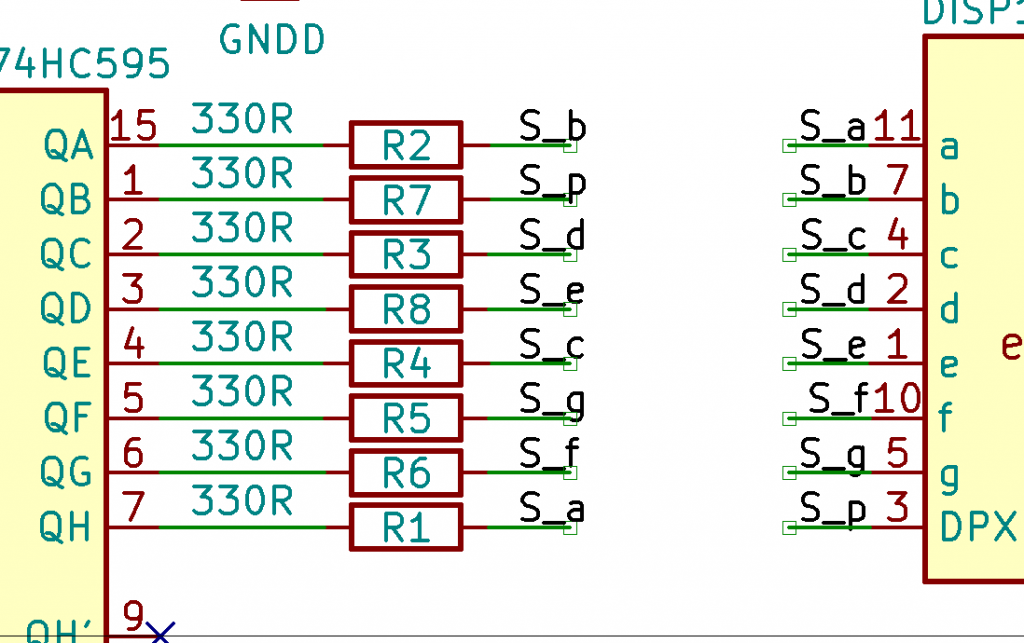
Setting the pins is very simple and we do it by software (in the defs.hpp file)::
#define SEG_A  0x80
#define SEG_B  0x01
#define SEG_C  0x10
#define SEG_D  0x04
#define SEG_E  0x08
#define SEG_F  0x40
#define SEG_G  0x20
#define SEG_DP 0x02
LATCH signal
Pin 12 of the HC595 is the LATCH signal (RCLK in the diagram, although each manufacturer calls it whatever they want). When you inject the bits into the HC595, they are NOT trasfered at the output immediately, but rather are saved in an internal register that is NOT connected to the outputs. Once all the bits are in place, it is then that you give the order to pass from the internal register to the outputs, managing to place all the bits in the output at the same instant of time.
The LATCH signal is the one that transfers the bits of the internal register to the outputs. Quite convenient. This signal is provided through a GPIO pin on your microcontroller and you can use whichever you want, as long as it is configured as an output pin.
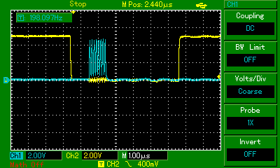
In the previous image we can see the LATCH signal in yellow, while the blue signal is SCLK.
OE (Output Enable)
There is a fourth control signal that is not mandatory or essential, but that will allow us to do interesting things like control the display brightness or make it blink; this signal is OE (output enable, active low). If you set it to a logic 1, the transistors at the output of the chip are deactivated, which translates into a black display. If you set it to a logic 0, the transistors at the output of the chip are activated normally as you have programmed them. If you don’t plan to use it, then leave it permanently connected to 0V.
IMPORTANT: The value of the output bits is NOT altered when OE is at a logic 1, only the output transistors are turned off. When you put OE back to a logic 0, whatever you have programmed will be present on the outputs again.
SRCLR
To finish the topic of the HC595 I want to mention pin 10 (SRCLR), which I effectively left at 5V permanently. A logic 0 on this pin sets the internal register bits to 0’s. We are going to do the same by software, so we save that line.
Finally I want to mention that the same circuit can be used for 3-digit modules; just don’t use pin D4 and do not install transistor Q4. Obviously you will have to notify the software of this decision, but it is very easy, as you will see.
Prototypes
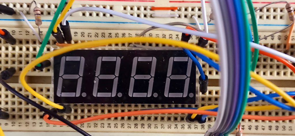
This is my first prototype on a breadboard. From here came the idea of creating an independent module that I could use in my other projects. Don’t you love the spagetti wiring?:
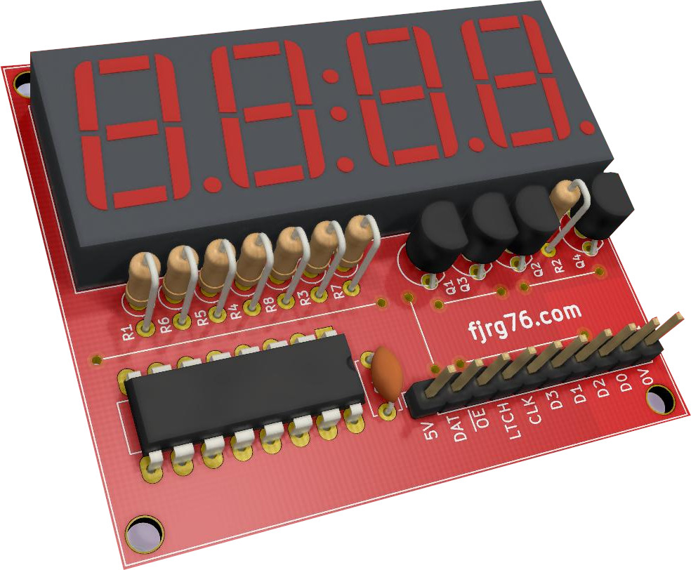
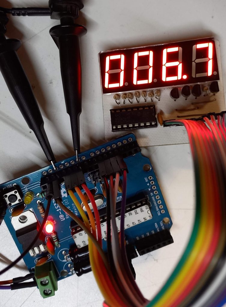
In the following image you can see the first printed circuit prototype. It is quite compact for using traditional mounting components.
The printed circuit, professionally made, looks like this from the artist’s point of view:
At the end of the article I’ll explain you how you can obtain the printed circuit design in PDF format so that you can make your own modules.
It was impossible for me not to use bridges in this design, but given its complexity, 5 of them is a good number. Remember that this is a single layer design so we all can create our own boards in our lab using common components.
Software
I wrote a small class for this module, which configures it and exposes 4 fundamental operations to the display:
class Display_HC595
{
private:
   const uint8_t* cathodes{nullptr};
   const uint8_t* digits{nullptr};
   uint8_t memory[ DISPLAY_HC595_CATHODES ];

public:
   Display_HC595();
   Display_HC595(Display_HC595&) = delete;
   Display_HC595& operator=(Display_HC595&) = delete;

   void clear();
   void print_str( uint8_t* str );
   void print_number( uint16_t num, uint8_t dp_pos, bool leading_zero = false );

   void begin( const uint8_t* cathodes, const uint8_t* digits );
   void update();
};
begin(): initializes the module.update(): Updates the content of the display. It must be called at regular intervals. In the example below I call it every 5 milliseconds.clear(): makes the display blank. Useful when you want to make it blink.print_str(): prints a 4-character text string. Don’t worry, in the example I’ll show you how to print much longer strings.print_number(): prints a number of up to 4 digits. You can set the decimal point position and you can also tell it if you want leading zeros.
Before writing to the module you must initialize it. To do this you must call the begin() function with a table that represents each of the different symbols you want to print out, and with an array that sets the pins where the digits are connected. The table and array are defined in the main file display_hc595.ino:
constexpr uint8_t digits_array[18] =
{
   SEG_A + SEG_B + SEG_C + SEG_D + SEG_E + SEG_F, // 0
   SEG_B + SEG_C,
   SEG_A + SEG_B + SEG_G + SEG_E + SEG_D,
   SEG_A + SEG_B + SEG_G + SEG_C + SEG_D,
   SEG_F + SEG_G + SEG_B + SEG_C,
   SEG_A + SEG_F + SEG_G + SEG_C + SEG_D,
   SEG_A + SEG_C + SEG_D + SEG_E + SEG_F + SEG_G,
   SEG_A + SEG_B + SEG_C,
   SEG_A + SEG_B + SEG_C + SEG_D + SEG_E + SEG_F + SEG_G,
   SEG_A + SEG_F + SEG_G + SEG_B + SEG_C + SEG_D, // 9

   SEG_A + SEG_B + SEG_C + SEG_E + SEG_F + SEG_G, // A
   SEG_C + SEG_D + SEG_E + SEG_F + SEG_G,
   SEG_A + SEG_D + SEG_E + SEG_F,
   SEG_B + SEG_C + SEG_D + SEG_E + SEG_G,
   SEG_A + SEG_D + SEG_E + SEG_F + SEG_G,
   SEG_A + SEG_E + SEG_F + SEG_G,                 // F

   SEG_G,                                         // -
   SEG_F + SEG_E + SEG_A + SEG_B + SEG_G,         // P
};

constexpr uint8_t cathodes_array[DISPLAY_HC595_CATHODES] = { 3, 4, 5, 6 };
As you can see I only set the numbers from 0 to 9 and the letters from A to F, and a couple of extra symbols. I did it this way because it’s what I need for a larger project I’m working on, but you can grow the table to include the entire ASCII table; It’s easy, but laborious. I have already done it for other similar projects, but for now that table works for me.
On the other hand, in the array of digits:
constexpr uint8_t cathodes_array[DISPLAY_HC595_CATHODES] = { 3, 4, 5, 6 };
I have established that I want to use the Arduino pins D3, D4, D5 and D6 to control the 4 digits. You can change them at your convenience, depending on your design and the microcontroller you are using.
By the way, this display can be used with boards other than Arduino UNO (or alike) with minimal changes.
Oh! You can also set a different association for the pins LATCH and OE signals to wherever it makes sense in your design (in the defs.hpp file):
#define DISPLAY_HC595_LATCH_PIN 9   // Arduino: D9
#define DISPLAY_HC595_OE_PIN    10  // Arduino: D10
In the same file you can establish if the module is 3 or 4 digits (including 2). Told you, it was easy!:
#define DISPLAY_HC595_CATHODES 4 // 4 digits module
Constructor
The constructor is empty because the respective initializations were made in the class declaration (C++11 allows it and is quite clean and convenient ). I also set that no copies of Display objects can be made; it doesn’t make sense since projects usually have only one display. If your project has two or more displays you will need to create separate objects.
update() method
This function, as I mentioned, is responsible for writing to the display and uses the SPI protocol. This protocol allows two or more devices to «hang» on their MOSI, MISO, and SCLK lines, but each one has to have a way to be discriminated against, since they don’t all have to be written to at the same time; normally each device that can be connected to the SPI bus has a trigger line. In the case of the HC595, this line is the LATCH signal.
If your project uses SPI with some other device, you must configure its respective activation line.
Example
I hate the Arduino super-loop because it forces us to program in a horrible ways, but in order to make the example in a sketch and have the possibility to share it with you, my kind readers, I gladly ran into a couple of problems.
*In the biggest project I’m working on (also on the Arduino platform), and from which I got the idea for this article, I use the FreeRTOS real-time operating system, which not only simplifies programming, but makes the code more efficient, clean and allows us to scale it without major inconveniences.
Basically I have 3 time bases:
- One of 5 milliseconds, which is the system time base (system tick),
- One of 100 milliseconds,
- and one of 1000 milliseconds.
I use the 5 milliseconds time base to update the display; and the other two to run a counter at those speeds, respectively.
In the example I have included 3 sub examples:
- A timer with a resolution of 1 second,
- A timer with a resolution of 100 milliseconds,
- The printing of a long text, which scrolls to the left.
These sub examples are inside a state machine so that they are executed one after the other. I hate the super-loop!
Static variables
When you study the code you will notice that many of my variables were set as static, and this is because:
I DO NOT USE GLOBAL VARIABLES WHERE THEY ARE NOT NEEDED
A major flaw of the Arduino platform, which has spread like the plague, is the indiscriminate use of the global variables. Well, I don’t use them if they are not properly and scientifically justified, as is the case with the display object of the Display class; when an object represents a hardware module, then we can, and should, make it global. In almost all other cases they are not justified.
Display_HC595 display; // global object
Standard Integers and portable code
Another feature I always use in my embedded programs is standard sized integers: uint8_t, uint16_t, uint32_t, etc. To use these definitions we must include the header file <stdint.h>.
If I ask you how many bits an integer (int) occupies on the Arduino UNO and how many bits an integer occupies on the Arduino Due, will you know the answer? The former is based upon an 8-bit chip and its integer size takes 16 bits, while the latter is based upon a 32-bit chip and its integer size takes 32 bits.
I personally prefer to use standard sizes as they allow me to port my programs from one chip to another more or less easily, or even simulate some parts of the code in the PC. For example, I usually start a program on the Arduino UNO but then I switch it into the Arduino Due in order to be able to debug it, and also, very often, I write a version of some function (such as print_str() and print_number()) on the PC and then I use it in one microcontroller (it’s a kind of simulation). That is why it is very important to me that the programs are portable.
Source code
You can grab the complete example source code from here.
EDIT 08/march/22: Now the display blinks! That is possible thanks to the OE HC595 input and a Blink class I’ve written.
Whats Next?
- If you want the same example using FreeRTOS (and consequently my KleOS project), let me know in the comments to write about it.
- Brightness. The idea of having exposed the HC595’s OE line is to control brightness (or also make the display flick). Although I already have it done, I did not add it in this article, but I will do it later. If you are interested let me know in the comments.
- More digits. To have more digits we can chain two 3 or 4 display modules, but the count of the pins to use grows linearly and it is then that we must think of auxiliary chips that encode the lines.
You can get the PCB in PDF format of this design for a couple of bucks so you can build it yourself with home-made tools and techniques. You’ll we redirected to an e-store so you feel confident on your purchase.
Have you heard about my free course (in spanish) on Arduino in real time for the UNO and Due Arduino boards?
Subscribe to my blog!

Mi perfil completo lo puede encontrar en: https://www.linkedin.com/in/fjrg76-dot-com/
- Arduino and ESP32 whims - diciembre 17, 2025
- Writing Scalable Firmware: Implementing the Command Pattern in C++ - diciembre 4, 2025
- Patrón de diseño de software Command para sistemas embebidos para los no iniciados - noviembre 30, 2025
3 COMENTARIOS