Digital dimmer (digital control of AC loads) using the Arduino UNO
(Lee este artículo en español AQUÍ)
Introducción
A dimmer is an analog device that controls the amount of power delivered to an alternating current (AC from here on) load. Control is achieved by means of a potentiometer that, together with other passive components, delays the activation of a power semiconductor known as TRIAC; the longer activation takes, the less power will be reaching the load.
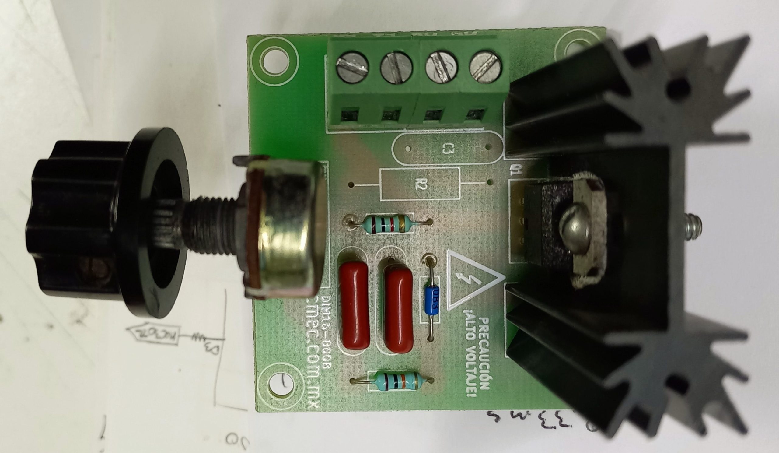
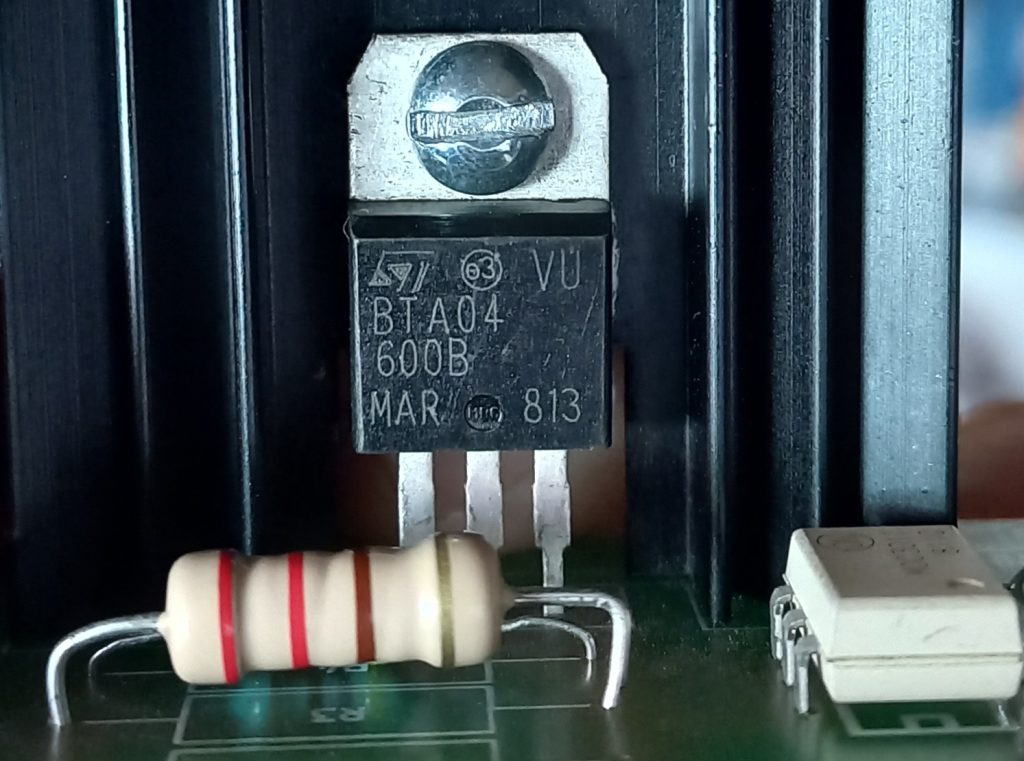
A TRIAC is a semiconductor used in AC applications that, once activated, allows the passage of electrical current to the load. An important point to keep in mind is that once the TRIAC has been activated, it cannot be easily deactivated (this statement applies mainly for DC applications). However, it has the property that when the AC returns to zero in each semi cycle, then it is automatically deactivated.
The potentiometer, together with a 1K resistor, a 100n capacitor (and a DIAC), form a time circuit (timer) that delays the arrival of power to the load. The project that I’m proposing keeps the TRIAC, but it will be controlled through a microcontroller timer, hence the name “digital dimmer”. However, depending on the final application the potentiometer could also be necessary.
Speaking of the potentiometer, this is one of several control possibilities, since you could also use two buttons (including the touch type): one to increase the power and another to decrease it; Or maybe you want to use an analog stick type control.
It is pertinent that you know that I started this mini project because I am working on a larger personal project that will use fuzzy control for a smd hot plate reflow: the fuzzy controller will calculate the delay that the timer will apply to activate the TRIAC in each half cycle of the AC, and consequently the power that the load will receive.
This project is built out of several elements:
- A zero crossing circuit for AC synchronization.
- A microcontroller timer.
- A potentiometer or buttons (depending on the final application of this digital dimmer).
- A power stage that sends energy to the AC load.
Sync circuit
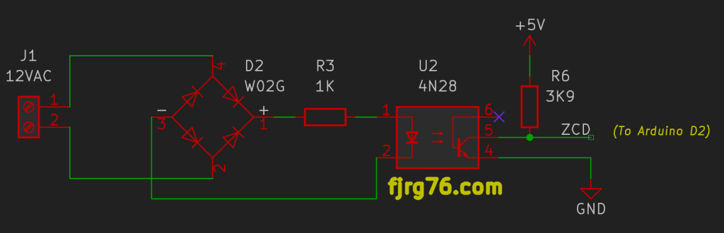
Whenever you want to control AC loads you will need a circuit that helps your controller to synchronize with the AC signal itself. In the case of the analog dimmer, its components do it automatically and naturally; however, in the case of the digital dimmer we will need extra components to build a zero crossing detector. For this subcircuit we have two possibilities: take the signal directly from the 127VAC line, or use a transformer that provides galvanic isolation. FOR OUR SAFETY I will use the latter.
For this zero crossing detector, in addition to the transformer, we are going to require an optocoupler to «square» the decreased AC sinusoidal signal. This square signal (along the fact that it’s electrically within the limits of our microcontroller) will be the synchronization signal that we will inject as an interrupt on the D2 pin of the microcontroller. This interruption will start the software timer in each half cycle of the AC, as I will detail later.
Why do we need synchrony?
Because you will get three undesirable effects if you activate the TRIAC arbitrarily:
- Your load will flicker. This effect is visually more noticeable when you control lamps.
- You are going to introduce noise to the AC network that will manifest itself as electromagnetic interference.
- You will hardly be able to control the load in the strict sense of the word (that is, it will take a lot of work for the system to reach a stable or equilibrium state: take as an example a SMD hot plate that needs to reach and stabilize at the 183 degrees; however, the real temperature obtained will always be oscillating around, and perhaps very far, from the desired value).
I should mention that there are different ways to implement the zero crossing detector; using the optocoupler is one of them and it has always worked for me. However, you might find configurations that use a transistor. Even, and with due care, you could use the ADC or comparator internal to the microcontroller to carry out the detection (someday I will try this).
IMPORTANT
Regardless of the technique you choose, ALWAYS use a transformer that galvanically isolates you from the AC mains voltage.
Timer
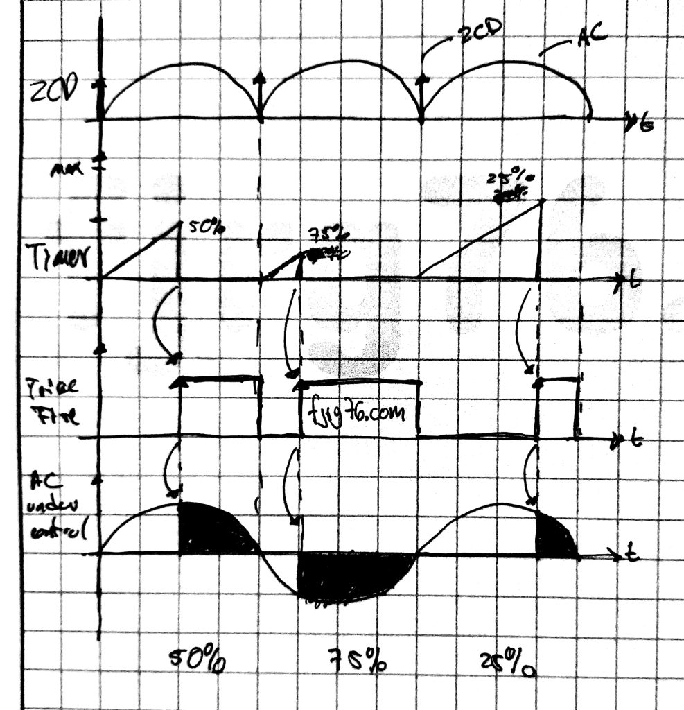
This is the most important subsystem of this project, yet the simplest: the timer will start counting from zero and ascending each time a synchronization signal arrives. Then, when the count reaches the preset value, it will send an activation signal to the circuit that controls the TRIAC:
This task is easy to achieve for any microcontroller but the configuration of each one will depend, of course, on the specific chip that we are using. For this project I will use the ATMEGA328 timer 2 (this microcontroller is the heart of the Arduino UNO board), nonetheless, the theory is the same for any other, such as the LPC microcontroller from NXP, the STM32 from ST, or the SAM from Microchip .
void setup()
{
   TCCR2A =
        (3<<4)         // COM2B1:0=0x3 -- Set OC2B on compare match, clear OC2B at BOTTOM
      | (3<<0);        // WGM21:0 =0x3 -- Fast PWM (along with WGM22 on TCCR2B)

   TCCR2B = (1<<3);    // WGM22   =0x1 -- Fast PWM (along with WGM21:0 on TCCR2A)

   // Start / stop is performed in another rutine. For start counting we would do:
   // TCCR2B = (1<<3)
   //        | (7<<0); // CS22:CS2:0   -- Choose CLK / 1024

   TCNT2 = 0;          // Counter.

   OCR2A = 128;        // Period. There will be 128 counts on one AC's semicycle

   OCR2B = 127;        // Duty cycle. 1 -> 100% power, 127 -> 0% power

   TIMSK2 = 0;         // Don't use any interrupt from the timer
   TIFR2 = 0;

   pinMode( TRIAC_PIN, OUTPUT );
   digitalWrite( TRIAC_PIN, LOW );

   pinMode( SYNC_PIN, INPUT_PULLUP );
   attachInterrupt( digitalPinToInterrupt( SYNC_PIN ), Sync_ISR, RISING );

   // ... more initialization here that doesn't interact with the timer ...
}
The timer is associated with pin D3 of the Arduino UNO and it’s configured so that as long as the counter does not reach the maximum count, the pin will remain in its low state. Once the counter has reached the maximum count, the pin goes high and the counter stops counting (in the datasheet we read: “Set OC2B on compare match, clear OC2B on BOTTOM”, mode: Fast PWM, table: 17- 6, pp. 129). This change from low to high on the pin D3 is the signal that will activate the power stage (of course without your intervention since this is carried out by hardware). At each new synchronization signal the pin is set low and the counter reset to zero to start the cycle again.
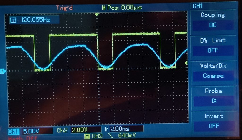
(Center) Activation pulse (D3) reaches half: Average power in the load.
(Right) Activation pulse (D3) arrives early: Too much power in the load.
The interrupt routine is as follows. At the end of this article you will find the complete source code.
// Sync ISR code
void Sync_ISR()
{
   timer_ctrl( STOP );
   // Don't update the timer registers while it's counting

   power.apply();
   // Update the timer registers with a new value (if any)

   digitalWrite( 13, (led_state=led_state?false:true) );
   // System is alive! (kind of)

   timer_ctrl( START );
   // Start the timer again
}
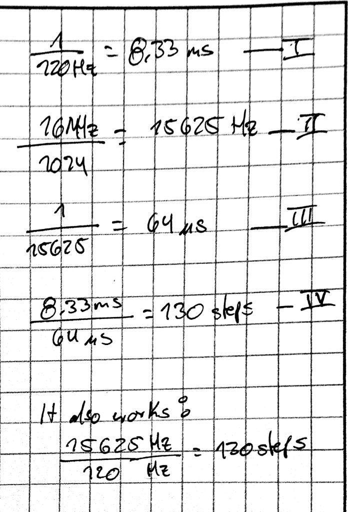
To finish this section, I would like to tell you that with the current configuration of the UNO’s timer 2 we are able to obtain up to 130 steps per semi-cycle (although I only used 128). Below I show you a summary of the calculations (these are also to my self from the future, when in 3 weeks I’ve forgotten why I did what I did), and then I’ll talk about the possible increase in resolution in the system (more steps in each half cycle).
Resolution
Can we get more steps in each cycle, that is, can we get more resolution? Yes and no. The exact answer depends on the number of bits in the timer registers. The registers in the ATMEGA328 timer 2, and specifically the TCNT2 counter register, are 8 bits wide, and the prescalers (frequency dividers) do not help much since they are few and fixed: 1024, 256 , 128, etc, so the maximum number of steps we can get is 130. To avoid weird divisions and for the sake of this proof of concept, I reduced the number to 128 (0-100% in steps of about 1; 100/128 to be exact).
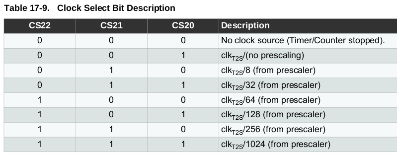
As you could see in the previous code, I used a divider with value 1024, whose maximum count for one half cycle of 60 Hz AC is 130 (1 / 120Hz = 8.33 ms; 130 steps * 64 us/step = 8.33 ms) and the value 130 fits perfectly in the 8 bits of the TCNT2 register. I cannot choose the prescaler with value 256 since the division of a complete half cycle would consist of 520 steps (higher resolution), however this value no longer fits in the 8 bits of the TCNT2 register.
One alternative for achieving more than 130 steps per semi cycle is to use the UNO’s timer 1, which is 16 bits wide; however, it is used by the Arduino subsystem for servo motors. You could use this timer instead as long as you agree with the fact that you could no longer control servos directly with the default terminals.
DON’T EVER TOUCH TIMER 0 on the Arduino UNO
What’s more, don’t even look at it!
On the other hand, 32 bits microcontrollers are ubiquitous these days (LPC(NXP), STM32(ST), SAM(Atmel), among many others). All include more powerful 32-bit timers and prescalers, so we could get hundreds or thousands of steps in each semi cycle. (In a previous exercise with an LPC812 I readily achieved 1000 steps per semi cycle; that is, 0-100% in steps of 0.1.) But there’s a catch.
Because the timer is not working in isolation, hundreds or thousands of steps per cycle will not always mean better system performance due to some circumstances beyond our control:
- The zero crossing detector is not perfect.
- The ADC is 10-bit, it has intrinsic errors, and with poor PCB design it could pick up ambient noise. (I used the ADC as a control for my proof of concept, as I’ll describe later.)
- Rounding and truncation errors for using decimal numbers.
- The fuzzy controller (for my oingoing project) doesn’t require a lot of precision as the algorithms will absorb the lack of it.
Why not directly use the PWM generated out of the Arduino UNO?
Perhaps you have already seen many circuits on the Internet where they «use» PWM to control AC loads; This technique does not work unless the PWM comes from an inverter and the load is connected to it. If the TRIAC is directly controlled (through the optotriac, of course) by the PWM coming out from your Arduino UNO, then you are going to face the 3 problems that I’ve mentioned in the previous section.
That’s the reason why I had to find a way to generate a single pulse every half cycle of the AC instead of using the direct PWM of the UNO.
Analog control (for the purposes of proof of concept and this article)
In order to test what we’ve done so far we must manipulate the control signal, and the easiest way is through a potentiometer connected to one channel of the ADC. Later on you could control it with two buttons, or with an analog stick, or with IR light (via a remote control), or by WiFi or Bluetooth, or with the voice through Alexa, etc.
Remember that we have splited the AC half cycle into 130 steps, but the ADC is 10 bits and it gives us 1024 steps, so we cannot do a 1 to 1 mapping between the potentiometer and the number of timer steps. Instead I’ve divided the value delivered by the ADC by 8, obtaining 128 steps (1024/8); that is, every 8 steps of the ADC correspond to 1 step of the timer, or in other words, we’re mapping 8:1.
Let me repeat that the objective of this subproject is the physical control of an AC load, which in control we call «the plant» (or «system»), and the amount of power that will be reaching the load will depend on what the fuzzy control algorithm has calculated. And a feature of fuzzy controllers is that they don’t need much precision; in fact, they are inherently imprecise: “near”, “far”, “warm”, “hot”, “very hot”, “small mistake”, “big mistake”, etc. So let’s not go crazy with precision.
Later I will be talking about this smd hot plate reflow, just be patient with me, one thing at a time.
Power stage
This stage is responsible for sending the trigger signal that comes out of pin D3 (this terminal is associated with timer 2) of the Arduino UNO to the TRIAC .
Remember that our microcontrollers work at 3.3VDC or 5VDC, but AC loads operate with 127VAC (in Mexico, USA and Canada) or 220VAC (in other countries), and we must avoid as much as possible that our low voltage integrated circuits come into direct contact with high voltage, for their safety and FOR US, mainly.
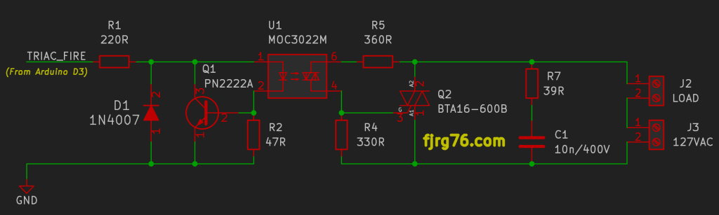
Be careful, the right hand components are HIGH VOLTAGE!
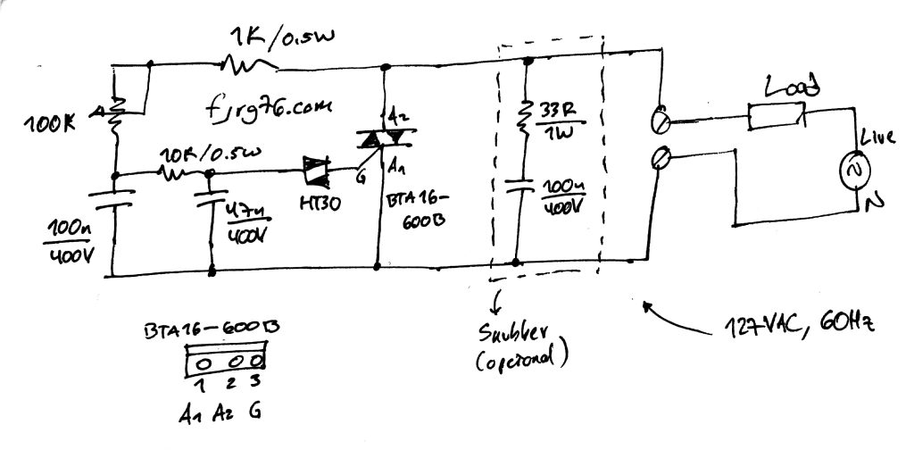
For the proof of concept I used an SSR prototype that I designed a while ago from the schematic above:
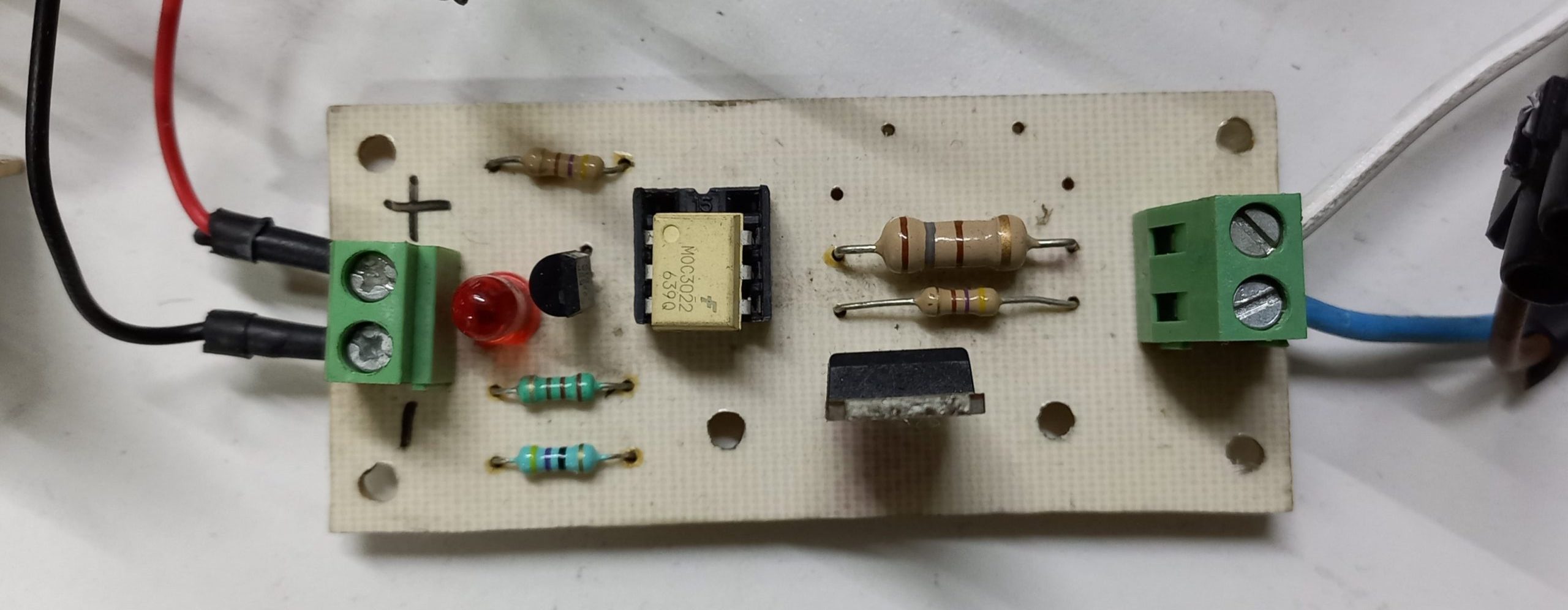
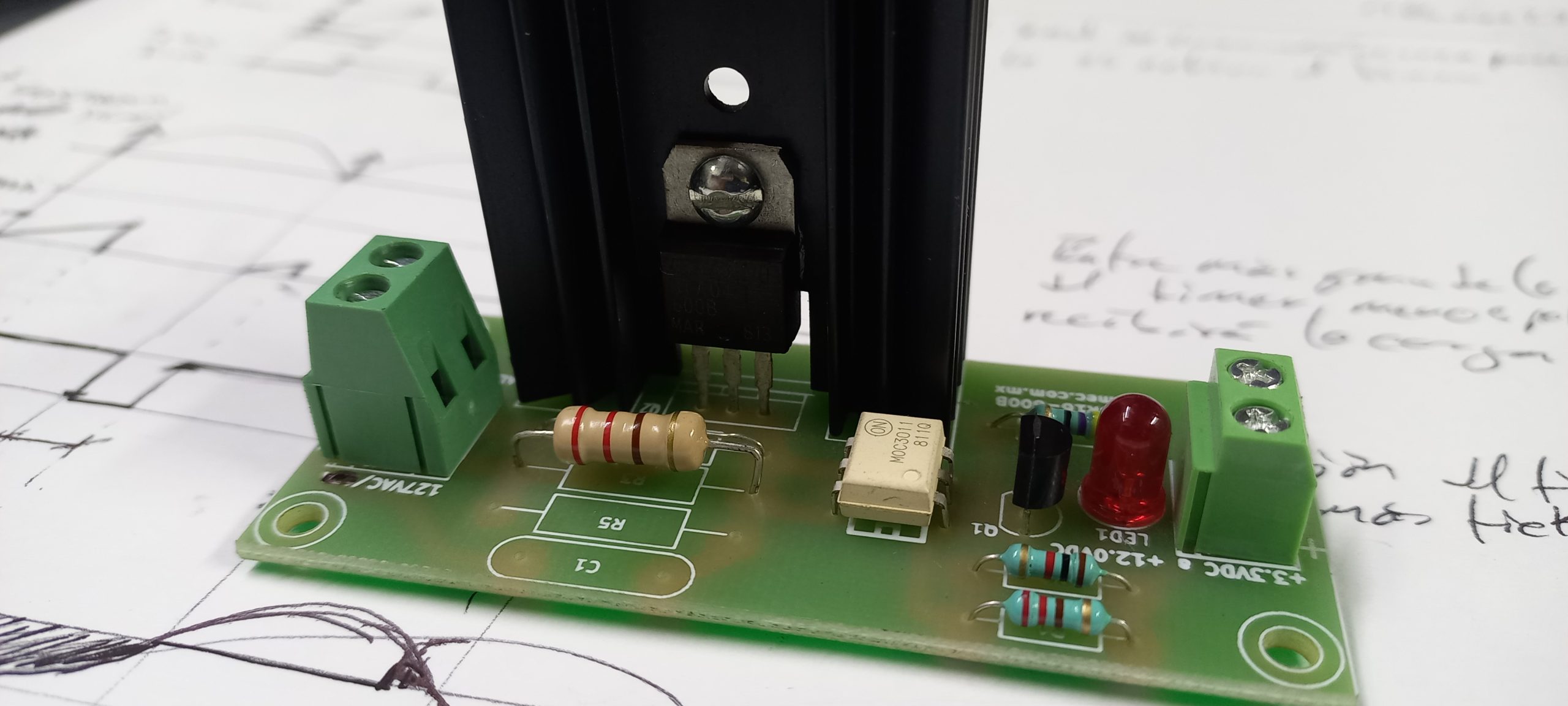
Right: Same SSR, but professionally manufactured. However I didn’t use it in this project due to the fact that the optotriac, which is soldered, includes a zero-crossing detector, which turns it useless for my goals.
(In this article you’ll find out a good explanation about SSRs. DISCLAIMER: I don’t have any commercial relation with the company.)
(In this entry of my alternate blog I show you a variant of the SSR to build it with homemade techniques.)
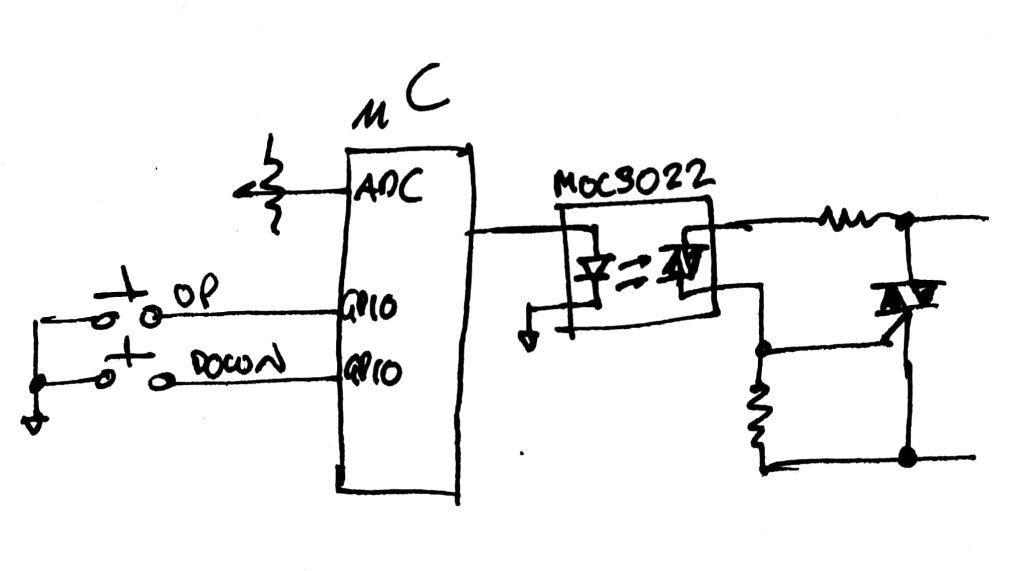
As an interface I used a device known as OPTOTRIAC (MOC3022) to provide optical isolation between low and high voltage, which is sufficient in most applications. If you need galvanic isolation, then you will need to use signal transformers. (Don’t use relays; these are too slow and could end their life in a few minutes.)
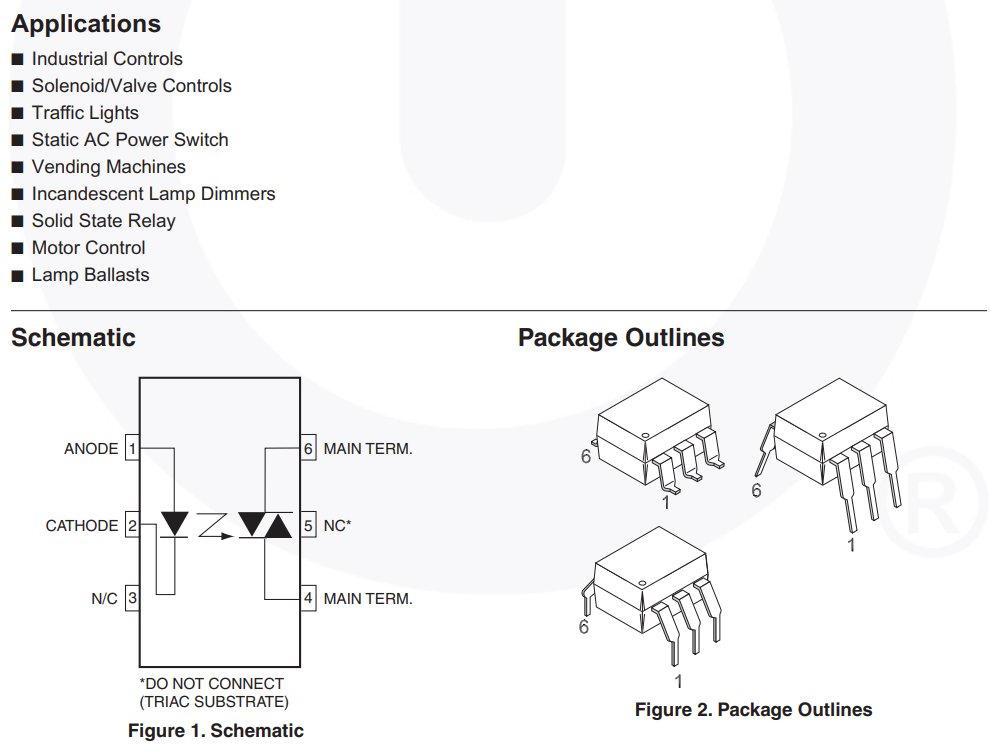
The optotriac receives the activation signal from pin D3 and optically transfers it to its internal triac (hence the name optotriac), which will generate the signal that the external TRIAC needs to activate. The TRIAC will turn off (stop conducting) when the AC signal returns to zero on every half cycle.
Interesting note: The triac in AC works as a kind of one-bit temporary memory: the timer (or external control) applies a «set» (1) to the THR(eshold) terminal, which causes the output to present a (1 ). This state will remain in such state until the “reset” (0) arrives, which is applied when the AC returns to zero, which causes the output to go to (0).
Snubber network
In applications where the loads are resistive (alu-chromel, ceramic or silicone heating elements) it is not necessary to add a circuit called “snubber network”, which consists, in its most basic form, of a resistor and a capacitor (R7 and C1 in the schematic). However, if the loads are reactive (motors, inductors), then such a network is mandatory. Fortunately, the project at hand uses resistive loads, so let’s not get into any more troubles. (But if you’re interested in learning more, ST has this very interesting application note on snubber networks for TRIACs.)
Complete project
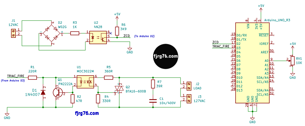
Below you will see the complete electronic circuit of the project and the associated code.
I haven’t designed a PCB for this project yet as I need to finish my fuzzy control application first; Right now I tested the concept with an Arduino UNO clone board of mine, a breadboard, a solid state relay also mine, and many jumpers.
Next you have the complete code. In case you can’t see it, then please visit GitHub to get it:
The schematic of the complete functional prototype is this:
Let me know if you build this project with the ATMEGA328 or any other microcontroller. In case you need very precise or very fine tuning control, then you should go for 32-bit or sacrifice the servo control subsystem of the Arduino UNO.
I would like to know if you use this circuit with a control other than the potentiometer, and also for what application you used it. Let me know in the comments!
¿Ya conoces mi curso gratuito de Arduino en tiempo real, utilizando el Arduino UNO o el Arduino Due y FreeRTOS?
If you like my articles, consider to subscribe to my blog!

Mi perfil completo lo puede encontrar en: https://www.linkedin.com/in/fjrg76-dot-com/
- Arduino and ESP32 whims - diciembre 17, 2025
- Writing Scalable Firmware: Implementing the Command Pattern in C++ - diciembre 4, 2025
- Patrón de diseño de software Command para sistemas embebidos para los no iniciados - noviembre 30, 2025
1 COMENTARIO