How to implement a monitor semaphore for Arduino with FreeRTOS
(Lee este artículo en español aquí.)
Years ago I designed this board, the UB-C328 based on the ATMEGA328. It exposes to the world 5 out of the 6 channels of the analog-digital converter, and the one that is not exposed is used to implement a keyboard based on a resistive ladder. So far so good.
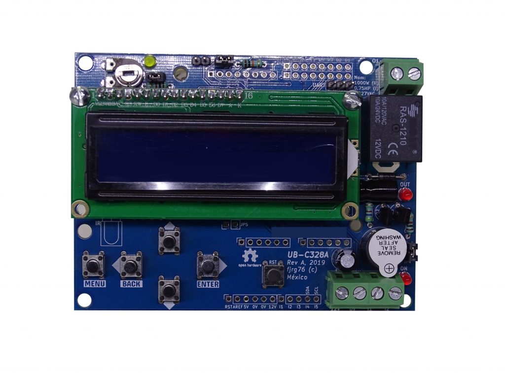
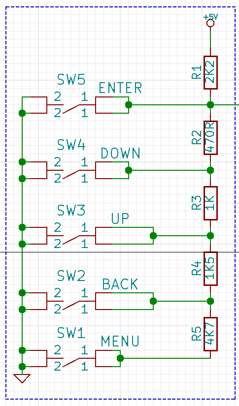
Troubles arose when I started writing concurrent applications for the UB-C328, that is, multi-tasking applications through the framework KleOS, which includes Arduino and the operating system FreeRTOS. The keyboard, or rather the ADC channel assigned to the keyboard, is read continuously every 1ms, while the rest of the channels can be read at any time. And that’s the problem: in concurrent systems you must be very careful about who, how and when you access a shared resource (in this case, the ADC).
I started getting erroneous, meaningless readings in an application where the UB-C328 was used to read the external temperature (through, of course, an ADC channel), being that the same code worked just fine in another (non-concurrent) program. After testing and analyzing the concurrent program, I figured out that the problem was that while in the task where the ADC performed the conversion in the temperature sensor, the task in charge of the analog-ladder keyboard interrupted the conversion, spoiling it. The ATMEGA328 datasheet states it crystal clear: a running conversion must not be interrupted with a newer one.
This problem, race condition , is typical of concurrent programs. To solve it I used a mechanism called monitor.
Monitors
A monitor is an abstract type (or more colloquially, a class in C++) that protects a shared resource by encapsulating a mutex and exposing only a set of operations that can be performed on the resource.
A shared resource can be either a memory area or a peripheral, which can potentially be accessed by two or more tasks at the same time with catastrophic results (like the ones I explained above). In my case the shared resource is the ADC, but it could also be a global variable, an array, the UART, the I2C (or TWI, for Atmel users), a display, a keyboard, etc.
Mutex Semaphore
A mutex (hereinafter simply mutex) is a binary semaphore with two outstanding features:
- The semaphore is given and it MUST be returned.
- The priority of the task that gets the mutex might be temporarily raised so that the task is not interrupted while it owns it so that it can finish its work as soon as possible. Once the task has finished with the shared resource its priority level is returned to its original value. When a task gets a shared resource and it does not return it, then you’ll face a harvesting problem (no other task can use the resource). Priority raising attempts to avoid this problem.
Although a mutex helps us to control the access to the shared resource, we’re not done yet. The monitor must expose a minimum set of operations on the resource; that is, the monitor should limit the use (and misuse) of it.
On this lesson from my free real-time Arduino course (in spanish, soon in english) I explain mutex semaphores in FreeRTOS and I also show the results of accessing the serial print (i.e. Serial.println()) out of control.
NOTE: To show you the use of the monitors in this article I am going to simplify the program so that we can concentrate on the details that are of interest for us and not get sidetracked with details about the UB-C328 board that are not relevant to the explanations.
- I will use two tasks with relative periods. Each task will read a different channel from the ADC (the resistive ladder-based keyboard is not important here).
- In order not to complicate the explanation I will use dynamically allocated tasks as the important thing right now is the monitor, not the way the tasks are allocated in FreeRTOS. (For more information about statically allocated tasks click here).
- I will use the Arduino platform through the framework KleOS. However, it would apply everywhere else.
Monitors in C++
As I mentioned, the monitor can be implemented through a C++ class:
#include <FreeRTOS.h>
#include <task.h>
#include <semphr.h>

class AdcMonitor
{
private:
   SemaphoreHandle_t mutex{ NULL }; // 1

public:
   AdcMonitor()
   {
      this->mutex = xSemaphoreCreateMutex(); // 2
   }

   int16_t read( uint8_t channel, uint16_t timeout )
   {
      int16_t ret_val = -1;

      if( xSemaphoreTake( this->mutex, timeout ) != pdFALSE ) // 3
      {
         ret_val = analogRead( channel ); // 4

         xSemaphoreGive( this->mutex ); //5
      }

      return ret_val;
   }
};
- The class
AdcMonitorencapsulates a mutex semaphore. - The class constructor creates the mutex (it can also be created with statically allocated memory , but is not the subject of this article).
- Here we try to get the mutex. If it is not obtained within the time indicated by the timeout, then the function ends indicating that it wasn’t obtained (using the sentinel value -1).
- Here we use the shared resource. The task that will use it must not block or take longer than expected.
- The mutex is returned so that other tasks can access the resource.
NOTE: Mutexes must be enabled in the FreeRTOSConfig.h configuration file setting the configUSE_MUTEXES constant to 1.
NOTE: I used the timeout semaphore’s property; but there is also the possibility of waiting forever (not recommended). If you would like to use this feature, then set the timeout to the value portMAX_DELAY, and in the FreeRTOSConfig.h configuration file set the constant INCLUDE_vTaskSuspend to 1.
Declaring monitor instances
The next step is for the tasks to access the shared resource through the monitor, how is it that each task will access it? We have two options:
- The monitor is created globally. Easy, but I’d think twice (global variables are bad, really bad). If we do this, any task not related to the ADC could access it (because of the global nature of the monitor). And if that wasn’t enough, an unrelated task could get it and never return it.
- The monitor is created locally and passed to each task that needs it. In this way, only the tasks that are related to the shared resource will have access to the monitor. The technique isn’t difficult, but it’s not very clear if you’re not familiar with void pointers,
(void*), and passing parameters to FreeRTOS tasks; however, if you’re interested in the topic I talk about it in this example of my free course (don’t get mad at me, my mother tongue is spanish, but let me know in the comments if you would like me to translate it to english. Give me a reason!)
Once again, we must concentrate on what is important. For that we will use form 1; but in production code you should use the form 2!.
AdcMonitor adc_monitor; // global instance of the monitor
Tasks
As I already mentioned, we will have two tasks competing for the ADC:
- One of them will have a higher priority than the other (to force it to be executed and prevent the ADC from being accessed sequentially).
- Both will have the same period to force them, once again, to compete for the ADC.
- Not relevant to the example, but one task will read the temperature from an LM35 sensor, while the other will do the same but with the MCP9700 sensor. The important thing here is that both use the same shared resource.
xTaskCreate( task_lm35,    "LM35", 128, NULL, tskIDLE_PRIORITY + 1, NULL );
xTaskCreate( task_mcp9700, "9700", 128, NULL, tskIDLE_PRIORITY,     NULL );
NOTE: For simplicity, and in order to stay focused on the use and implementation of the monitor, I created both, the tasks and the mutex, with dynamically allocated memory; however, in production code you should prefer the statically allocated memory way: xTaskCreateStatic() and xSemaphoreCreateMutexStatic(), respectively.
task_lm35
This task reads from one ADC’s channel through the monitor and converts the reading to degrees centigrades:
#define LM35_ADC_CHANNEL 0
#define LM35_TIMEOUT     50
#define LM35_PERIOD      500
void task_lm35( void* pvParameters )
{
   (void) pvParameters;

   TickType_t last_wake_time = xTaskGetTickCount();

   while( 1 )
   {
      vTaskDelayUntil( &last_wake_time, pdMS_TO_TICKS( LM35_PERIOD ) );

      int16_t ret_val = adc_monitor.read( LM35_ADC_CHANNEL, pdMS_TO_TICKS( LM35_TIMEOUT ) ); // 1

      Serial.print( "LM35: " );
      if( ret_val >= 0 ) // 2
      {
         float temp_lm35 = ( ret_val * 5.0 * 100.0 ) / 1024.0;
         Serial.println( temp_lm35 );
      }
      else // 3
      {
         Serial.println( "TIMEOUT" );
      }
   }
}
- Observe how the ADC reading is performed: we do it through the adc_monitor instance of the AdcMonitor class instead of directly with the Arduino
analogRead()function, which is actually encapsulated inside the monitor. It is that easy (and safe)!. - If the ADC was obtained before the timeout expired, then we use the read. In this case we convert the reading into degrees centigrades.
- Otherwise, we notify that we did not get the resource before the timeout expired and we take the pertinent measures. Using the timeout allows the system not to crash because of starvation. The recovery routine should be written according to the needs of the application.
The other task, task_mcp9700, is almost identical, so I won’t put it here, but you’ll see it later in the full example. Aside from using another channel of the ADC, the formula for converting to degrees Celsius is also different, but that’s not relevant to the example.
If you want to know more about the conversion formula, click here, which will take you to my alternative blog; and if you want to know how you can increase the accuracy of this sensor, then hit click here.
You will notice that in both tasks I used the vTaskDelayUntil() function instead of vTaskDelay(). I did this so that both tasks would take the ADC (almost) at the same time. vTaskDelay() introduces time offsets that would prevent both tasks from competing for the ADC (which would be ideal, but not for this example).
If you want to know more about the periodic tasks in FreeRTOS, click here and here.
Complete example
Here is the complete example of this article:
#include <stdint.h>

#include <FreeRTOS.h>
#include <task.h>
#include <semphr.h>

class AdcMonitor
{
private:
   SemaphoreHandle_t mutex{ NULL };

public:
   AdcMonitor()
   {
      this->mutex = xSemaphoreCreateMutex();
   }

   int16_t read( uint8_t channel, uint16_t timeout )
   {
      int16_t ret_val = -1;

      if( xSemaphoreTake( this->mutex, timeout ) != pdFALSE )
      {
         ret_val = analogRead( channel );

         xSemaphoreGive( this->mutex );
      }

      return ret_val;
   }
};


//----------------------------------------------------------------------
// Monitor instance:
//----------------------------------------------------------------------
AdcMonitor adc_monitor;


#define LM35_ADC_CHANNEL 0
#define LM35_TIMEOUT 50
#define LM35_PERIOD 500
void task_lm35( void* pvParameters )
{
   (void) pvParameters;

   TickType_t last_wake_time = xTaskGetTickCount();

   while( 1 )
   {
      vTaskDelayUntil( &last_wake_time, pdMS_TO_TICKS( LM35_PERIOD ) );

      int16_t ret_val = adc_monitor.read( LM35_ADC_CHANNEL, pdMS_TO_TICKS( LM35_TIMEOUT ) );

      Serial.print( "LM35: " );
      if( ret_val >= 0 )
      {
         float temp_lm35 = ( ret_val * 5.0 * 100.0 ) / 1024.0;
         Serial.println( temp_lm35 );
      }
      else
      {
         Serial.println( "TIMEOUT" );
      }
   }
}


#define MCP9700_ADC_CHANNEL 1
#define MCP9700_TIMEOUT 50
#define MCP9700_PERIOD 500
void task_mcp9700( void* pvParameters )
{
   (void) pvParameters;

   TickType_t last_wake_time = xTaskGetTickCount();

   while( 1 )
   {
      vTaskDelayUntil( &last_wake_time, pdMS_TO_TICKS( MCP9700_PERIOD ) );

      int16_t ret_val = adc_monitor.read( MCP9700_ADC_CHANNEL, pdMS_TO_TICKS( MCP9700_TIMEOUT ) );

      Serial.print( "9700: " );
      if( ret_val >= 0 )
      {
         float temp_9700 = ( 500.0*ret_val - 51200.0 ) / 1024.0;
         Serial.println( temp_9700 );
      }
      else
      {
         Serial.println( "TIMEOUT" );
      }
   }
}


#define PERIOD_HIGH 20
#define PERIOD_LOW  980
void heart_beat( void* pvParameters )
{
   (void) pvParameters;

   pinMode( 13, OUTPUT );

   bool led = false;

   while( 1 )
   {
      vTaskDelay( pdMS_TO_TICKS( !led ? PERIOD_LOW : PERIOD_HIGH ) );
      digitalWrite( 13, ( led = !led ) );
   }
}


void setup()
{
   xTaskCreate( task_lm35,    "LM35", 128, NULL, tskIDLE_PRIORITY + 1, NULL );
   xTaskCreate( task_mcp9700, "9700", 128, NULL, tskIDLE_PRIORITY,     NULL );
   xTaskCreate( heart_beat,   "HBT",  128, NULL, tskIDLE_PRIORITY,     NULL );

   Serial.begin( 115200 );
   Serial.println( "monitor_ADC.ino" );

   vTaskStartScheduler();
}


void loop()
{
   // nothing in here when using a kernel
}
A running of this program looks like this:
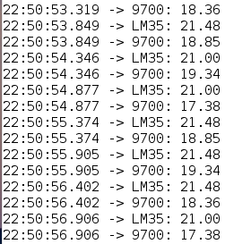
Aside from the differences in temperature, which are not relevant to this article, notice that there are no incorrect or strange numbers.
On this lesson, to which I had already referred you, the differences between using and not using the monitor are remarkable; I’ll leave you here an output of the test program that I used there without a monitor:

when the correct (or expected) output is like this (here I already used monitor):
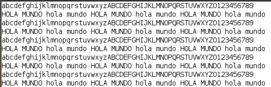
CURIOUS NOTE: You may have already noticed that I used the Serial.print() printing utility in both tasks for the example in this article. This utility is also a shared resource, and in order to avoid the issues shown for the running mess output , I kept the serial outputs as short as possible, since today’s topic is about the ADC. In production code the serial printing utility should have its own mutex.
I’ve shown two shared resources running on the same system:
- The ADC.
- The serial communications port.
However, there are also other shared resources for the same system, which in more complex concurrent programs, should also use the monitors:
The I2C interface. In this other project, UB-PLR328 (a programmable logic controller (PLC) based on Arduino and the ATMEGA328, programmed using FreeRTOS), I use this interface to access 3 different elements:
- The real time clock MCP79410.
- Two GPIO expanders PCF8574. One for writing to a 16×2 LCD display, and one for reading from a keyboard.
As you can guess, the 3 elements are not timely related, and if you don’t use a control system, the results would be disastrous. Here you can see a video where the 3 elements are working along.
The SPI interface. It faces the same problem as the I2C protocol: many devices can be connected to the same bus; therefore, a monitor should control access.
In general, any interface to which different devices can be «hung» to its bus (RS-422/485, CANbus, LIN, SPI, I2C, etc) will need an access control system if the program is carried out concurrently.
Finally, you might also want to read a topic close related to monitors: condition variables (here).
Start writing real time programs for the Arduino UNO:
Grab my framework KleOS!
Looking for professional KiCAD PCB designer?
I’m on Fiverr. Designs from 30USD!
Have you heard about my free course (in spanish by now) on Arduino in real time for the UNO and Due Arduino boards?
If you enjoyed this article consider to subscribe it.

Mi perfil completo lo puede encontrar en: https://www.linkedin.com/in/fjrg76-dot-com/
- Arduino and ESP32 whims - diciembre 17, 2025
- Writing Scalable Firmware: Implementing the Command Pattern in C++ - diciembre 4, 2025
- Patrón de diseño de software Command para sistemas embebidos para los no iniciados - noviembre 30, 2025
1 COMENTARIO