How to make your binary peripherals blink (almost) without your intervention: a class in C++
(Lee este artículo en español aquí.)
Introduction
We all have designed systems that include several binary peripherals (LEDs, relays, buzzers, etc.) that must be activated and deactivated independently and under different conditions.
For example, a circuit with two LEDs (one red and one blue), a relay and a buzzer.
- The red LED should blink continuously with an ON time of 500ms, and an OFF time of 500ms.
- The blue LED should blink with an ON time of 50ms and an OFF time of 2950ms, for 10 cycles each time data arrives at the serial port.
- The relay must be activated once during 10 seconds when the algorithm indicates it.
- And in case of any system failure, the buzzer should be activated for 1000ms and deactivated for 4000ms and repeat the cycle until the user presses a certain button.
If this timing is already complex in itself, imagine that you have to implement it inside the (horrible) super loop of Arduino, things get worse!
Can we solve it? Of course, using a C++ class, which will take control of the peripheral once the object has been configured.
In several projects that I have been working on in Arduino (check my blog to know them) I ran into the problem just described, and pretending to control each binary peripheral separately would have resulted in a (programming) disaster.
The best solution is to use a real-time operating system, such as FreeRTOS, and take advantage of the software timers it includes. However, few Arduino users know and use it, and I wanted a solution that most electronic enthusiasts can use painlessly, so I came up with the idea of writing a simple C++ class that was easy to use and reusable between different platforms.
With this class you will be able to:
- Establish the polarity of the binary peripheral, that is, if it is active high or low.
- Program the binary peripheral to activate and deactivate only once.
- Program the binary peripheral to turn on and off for a certain number of cycles, with independent on and off times. And you can always stop it under the control of an instruction.
- Program the binary peripheral to turn on and off in an infinite loop, with independent turn-on and turn-off times. And you can always stop it under the control of an instruction.
- Control various peripherals independently, even within the Arduino super-loop!
Keep reading to know more about this versatile class.
How it works?
The heart of the class is a finite state machine (FSM) whose behavior depends on the way you’ve programmed the peripheral. Once the programming is done and the peripheral is enabled, the FSM will take care of the rest, allowing your program to do useful work and not worry about the details:
The following image is a representation of the FSM as a flow chart:
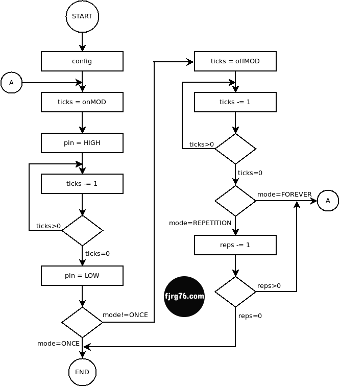
And this is the actual FSM’s code. Note that it’s only two states:
   void Blink::state_machine()
   {
      if( this->running )
      {
         switch( this->state )
         {
            case 0:
               --this->ticks;
               if( this->ticks == 0 )
               {
                  write( this->pin, static_cast<uint8_t>(this->polarity) ^ PIN_LOW );

                  if( this->mode == eMode::REPETITIVE or this->mode == eMode::FOREVER )
                  {
                     this->ticks = this->ticks_offMOD;
                     this->state = 1;
                  }
                  else
                  {
                     this->running = false;
                  }
               }
               break;

            case 1:
               --this->ticks;
               if( this->ticks == 0 )
               {
                  if( this->mode == eMode::REPETITIVE )
                  {
                     --this->times;
                     if( this->times == 0 )
                     {
                        this->running = false;
                     }
                  }

                  if( this->running )
                  {
                     this->state = 0;
                     this->ticks = this->ticks_onMOD;

                     write( this->pin, static_cast<uint8_t>(this->polarity) ^ PIN_HIGH );
                  }
               }
               break;
         }
      }
   }
NOTE: I must clarify that the FSMs (it is one per peripheral) must be called at regular and constant time intervals. If your system has a timer interrupt (ISR) (from a microcontroller timer), then you can place the FSMs there; if you are using the horrible Arduino’s super-loop, then you’ll have to place the FSMs as indicated later.
As an added value of this class, and in general, of software engineering, is that you should start thinking on event–driven programming terms, which is a very useful technique and much better than it sounds, and hopefully I think it won’t interfere with your usual way of programming.
Stop worrying, I’ve got good news: you do NOT have to program the FSMs, they are already part of the class itself; you just have to place them in the right place and call them at the right time.
FSMs in an ISR
For example, if you have access to a timer ISR in your microcontroller you could do the following:
ISR( Timer1 )
{
   lcd_backlight.state_machine();
   led13.state_machine();
   buzzer.state_machine();
}
Notice that the (hypothetical) ISR is controlling 3 binary peripherals through each other’s FSM. It’s that simple.
FSMs in the Arduino super-loop
If you’re using Arduino, then you should place a tick and call the FSMs each time:
void loop()
{
   static unsigned long last_time = 0;
   unsigned long now = millis();
   if( ( now - last_time >= ( SYSTEM_TICK ) ) )
   {
      last_time = now;
      led13.state_machine();
      buzzer.state_machine();
      relay.state_machine();
   }
}
Later on I’ll show a complete example using this technique.
Blink class
Once we’ve known the heart of the class, let’s see its public methods:
class Blink
{
public:
   enum class eMode: uint8_t { ONCE, REPETITIVE, FOREVER };
   enum class ePolarity: uint8_t { ACTIVE_HIGH, ACTIVE_LOW };

   Blink();

   Blink& operator=(Blink&) = delete;
   Blink(Blink&) = delete;

   void begin( uint8_t pin );
   void set( eMode mode, uint16_t ticks_on, uint16_t ticks_off = 0, uint16_t times = 1);
   void start();
   void stop();
   void state_machine();
   bool is_running();
   static Output_fn write;

private:
   // private members are not relevant in this moment
};
How to use it
1 Linking the software with the hardware
The Blink class is independent of any platform and microcontroller, so it is necessary to inject it a function that activates and deactivates the associated peripheral. This function is unique for the whole system (in other words, shared by all objects), since we are assuming that all peripherals are activated and deactivated in the same way.
1. The function you have to inject must have the following signature, which follows that of the Arduino UNO’s digitalWrite() function:
void digitalWrite( uint8_t pin, uint8_t pin_state );
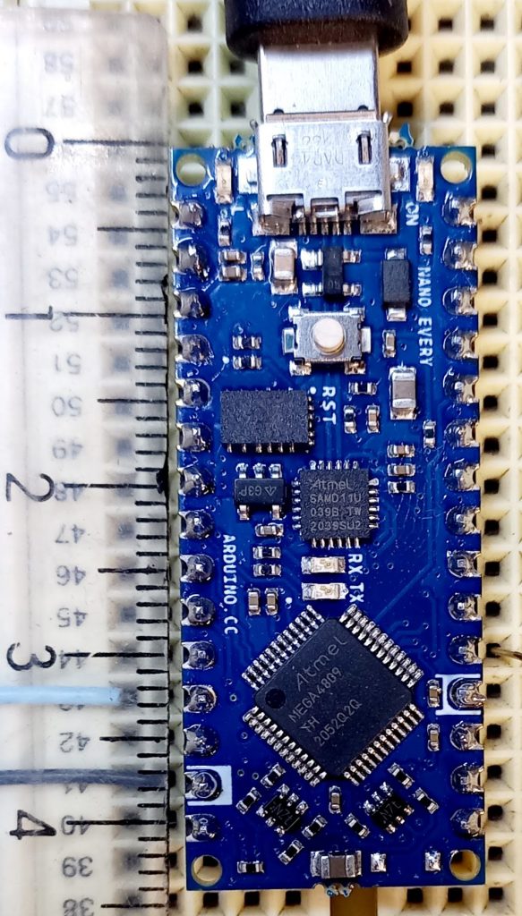
NOTE: The signature of the Arduino Nano Every digitalWrite() function is different in the types of the arguments, and in the companion example I’ll show you how to fix it (since for this article I used such board instead of the UNO). And this solution will work for any other micro and platform.
2. Now it’s time to inject the function to activate (ON) and deactivate (OFF) binary peripherals that you write in step 1. At the global scope (outside any function) write the following statement:
Output_fn Blink::write = digitalWrite;
Deep down the Blink class turns ON or OFF the peripherals calling the static method write().
NOTE: The symbols Output_fn and write must be fully qualified:
fjrg76::Output_fn fjrg76::Blink::write = digitalWrite;
fjrg76 is the namespace the class belongs to (for organization purposes). However, such expression can be simplified if you use the C++ using-declarations (and this is the form I used in the full example below) feature:
using fjrg76::Blink;
using fjrg76::Output_fn;

Output_fn Blink::write = digitalWrite;

// we also use the using-declarations to declare the objects (more on this later)
Blink led13;
Blink buzzer;
Blink relay;
2 Building the objects
Creating the objects requires two steps following the Arduino philosophy (for hardware-related objects, and it isn’t that bad actually):
- Create “empty” objects.
- Configure the hardware for those objects.
Recall the last time you declared the Serial, Wire or SPI objects in Arduino. You don’t. It is not important since the system does it for us, however, when you want to actually use any of them then you do have to call their .begin() method (usually in the setup() function) to configure the corresponding piece of hardware.
We’ll do the same, although you can do it the way you like that fits the system you are developing.
If you’ve read my other articles you will already know that I am not a fan of global variables, but in the case of hardware we can break the rules, since sometimes there is no alternative. And today is one of those days.
For our example assume a system with 3 binary peripherals: an LED, a relay, and a buzzer, each one controlled independently. The LED is active high, while the relay and buzzer are active low.
1. “Empty” objects are created with global scope (ie, as global variables):
#include "Blink.hpp" // don't forget to include the header!

// don't also forget that we're using the C++ using-declarations as above:
Blink led13;
Blink buzzer;
Blink relay;
At this point, none of the objects have an associated peripheral (the hardware). We will solve it in the next step.
2. Now we are going to associate each object with a microcontroller pin. We’ll do this inside the Arduino setup() function, or anywhere before entering the main loop of the program (all embedded programs have a main loop), using the .begin() function:
void setup()
{
   pinMode( 13, OUTPUT ); // on-board LED       (active high)
   pinMode( 2, OUTPUT );  // simulates a buzzer (active low)
   pinMode( 3, OUTPUT );  // simulates a relay  (active low)

   digitalWrite( 13, LOW );
   digitalWrite( 2, HIGH );
   digitalWrite( 3, HIGH );


   // objects binding:

   led13.begin( 13 );
   // ACTIVE_HIGH by default

   buzzer.begin( 2, Blink::ePolarity::ACTIVE_LOW );
   relay.begin( 3, Blink::ePolarity::ACTIVE_LOW );

   // more initialization here . . .
}
The .begin() method takes 2 arguments:
- A pin number. This argument is required.
- The polarity of the pin. It is used to tell the class if the pin is activated with a logical value 1 (active high) or with a logical value 0 (active low). This argument is optional; the default polarity is active high.
And that’s it for the objects construction.
IMPORTANT: I am assuming that once we have created the object-hardware relationship, it will not change during the execution of the program (and there is no a compelling reason to change).
3 Installing the FSMs
The next thing to do is to place the FSMs of each object in the indicated place, that is, in a timer ISR or in a pseudo tick inside the Arduino super-loop.
I’ve already shown how to install the FSMs in a timer ISR, which turns to be very easy. So now I’m going to show you how to install the FSMs inside the Arduino’s super-loop.
Get a regular and constant time base, which can be done using the Arduino’s millis() function, and then install the FSMs, as indicated:
#define SYSTEM_TICK 10 // in milliseconds
#define MS_TO_TICKS( x ) ( (x) / ( SYSTEM_TICK ) )
void loop()
{
   static unsigned long last_time = 0;
   unsigned long now = millis();
   if( ( now - last_time >= ( SYSTEM_TICK ) ) ) // <- Pseudo tick
   {
      last_time = now;

      led13.state_machine();
      buzzer.state_machine();
      relay.state_machine();
   }

   // Regular Arduino's code:
}
The SYSTEM_TICK constant sets how many milliseconds takes each tick in your time-driven system. You set this value based upon your needs; typical values could be: 10ms, 50ms, 100ms. I don’t recommend 1ms on the Arduino platform because the rest of your code could use more than that and the system will start to shift the time. It’s not bad, but it’s not good either. For today’s example, the 10ms value is perfect (in another of my projects, here, I set the value for 5ms).
The reasons for including a conversion formula from milliseconds to system ticks, MS_TO_TICKS() is twofold:
- As most of us are humans we understand ourselves better in milliseconds, and
- You won’t have much trouble if you ever want to change the time base.
The last_time variable is marked as static so that it holds its value between calls.
Everytime the expression if( ( now - last_time >= ( SYSTEM_TICK ) ) ) evaluates to true, it indicates that a tick has arrived and it is time to update the FSMs.
Told you it was very simple… more or less, let’s have some bad news.
Nothing comes for free in life
For this to work you need to not use blocking functions, such as the (in)famous Arduino’s delay(). The delay() function keeps the CPU for itself for as long as the time programed and doesn’t allow any other code to do any useful work; that is, a delay(1000) would mean that the FSMs will not be updated for a period of 1s; and delay(10000) would mean that the FSMs will not be updated for a period of 10s.
In this article I show you a way to convert your programs to event (time) driven programming. Don’t hate me, it’s all because of the Arduino super-loop!.
A timer ISR does not have this problem, since it is precisely an interrupt that will take control of the CPU and update the FSMs regardless of whether any function has kept the CPU for a long.
4 Configuring and using the objects
The next step is to control our binary peripherals using the the Blink class methods.
1 Simple example
I want to start easy and for this I am going to use the led13 object and modify the setup() function a little bit:
void setup()
{
   // same as before

   led13.set( Blink::eMode::FOREVER, MS_TO_TICKS( 100 ), MS_TO_TICKS( 900) );
   led13.start();
}
The .set() method takes 4 arguments:
- The mode. Here we establish in which of the 3 modes the peripheral is going to work:
Blink::eMode::ONCE: It is activated once.Blink::eMode::REPETITIVE: The loop repeats n times.Blink::eMode::FOREVER: The cycle repeats indefinitely.
- The number of ticks that the peripheral will be at the active level. I recommend you use the
MS_TO_TICKS()macro to convert milliseconds to ticks. - The number of ticks that the peripheral will be low. I recommend you use the
MS_TO_TICKS()macro to convert milliseconds to ticks. This argument is not used in modeBlink::eMode::ONCE. - The number of repetitions for the ON/OFF cycle when
Blink::eMode::REPETITIVEmode has been selected. It’s optional and it’s not used in the other two modes (you don’t have to give it a value in the other modes, as the next example will demonstrate).
In the previous example, the .set() method has configured the led13 object to blink forever, with an active time (in the ON state) of 100ms and an inactive time (in the OFF state) of 900ms.
After you’ve configured the pin it is necessary to call the .start() method for the cycle to start. You can stop the cycle at any time by calling the .stop() method.
2 More complicated example
This example is an extension of the previous one by adding the other two objects, the buzzer and the relay. It gets a bit complicated, but don’t get lost in the details. What I want you to notice is that the peripherals are controlled independently:
void setup()
{
   // same as before . . .

   led13.set( Blink::eMode::FOREVER, MS_TO_TICKS( 100 ), MS_TO_TICKS( 900 ) );
   led13.start();

   buzzer.set( Blink::eMode::REPETITIVE, MS_TO_TICKS( 100 ), MS_TO_TICKS( 100 ), 10 );

   relay.set( Blink::eMode::ONCE, MS_TO_TICKS( 2000 ) );

   // more initializations ...
}
The buzzer’s object cycle is set to 10 repetitions, with ON/OFF times of 100ms/100ms every 5 seconds (as shown below). The relay object only fires once for 2 seconds every 7 seconds.
Note that the buzzer and relay objects do not have the start instruction yet (the .start() method). This will be called in the super-loop after a complex timing:
void loop()
{
   static unsigned long last_time = 0;
   unsigned long now = millis();
   if( ( now - last_time >= ( SYSTEM_TICK ) ) )
   {
      last_time = now;

      led13.state_machine();
      buzzer.state_machine();
      relay.state_machine();


      static uint16_t seconds = MS_TO_TICKS( 1000 );
      --seconds;
      if( seconds == 0 )
      {
         seconds = MS_TO_TICKS( 1000 );


         static uint8_t counter0 = 5;
         --counter0;
         if( counter0 == 0 )
         {
            counter0 = 5;

            buzzer.start(); //<- Starts the cycle for the buzzer object
         }


         static uint8_t counter1 = 7;
         --counter1;
         if( counter1 == 0 )
         {
            counter1 = 7;

            relay.start(); //<- Starts the cycle for the relay object
         }
      }
   }


   // Your other Arduino's code:

}
5 Using a function other than digitalWrite() from the UNO
As I mentioned, the class’ function that interacts with the hardware uses the following signature, which follows the Arduino UNO:
void digitalWrite( uint8_t pin, uint8_t pin_state );
But when I test the class on an Arduino Nano Every board (which uses the ATMEGA4809 chip) it didn’t compile because of the function signature for such board is different:

So I had to write an adapter function, my_digitalWrite():
void my_digitalWrite( uint8_t pin, uint8_t pin_state )
{
   digitalWrite( pin, pin_state ); // from any Arduino
}
This function is the one that I inject when I link hardware to software in the full example:
Output_fn Blink::write = my_digitalWrite;
This trick might also work for you when you’re using a different platform, like those of ST or NXP:
void my_digitalWrite( uint8_t pin, uint8_t pin_state )
{
   Chip_GPIO_SetPinState(LPC_GPIO_PORT, 0, pin, pin_state ); // NXP style
}
NOTE: You’ll have to struggle a bit when the peripherals you want to control belong to ports other than port 0 (as in the above code). If you face any problems, let me know it in the comments; everything is solved with a conversion table.
Full Example
Here is a link to a Git repository where you can download or fork the full example. It includes:
- The Blink module in two files: Blink.hpp and Blink.cpp. Don’t forget to include the Blink.hpp header file in every file you use the class in. And don’t forget to link against the Blink.cpp file when you run the compiler instruction, either. But don’t worry, Arduino and many other IDEs already have done it for you: just include the module as part of the project you’re working on.
- The blinking_class.ino file which is the example code on which I based this article and which shows you everything we are talking about today. If you use a system other than Arduino, you must port the example to your platform (it’s very simple).
The example is ready to run on any Arduino, but with minimal changes you can use it on any other platform.
The code also includes documentation using the Doxygen format.
Conclusions
In several projects in which I am working on ( linke this and this (in spanish for now, english soon)) this class has saved me a lot of time, and fortunately, it has forced me to write code in Arduino using event-driven programming model, situation that I’d posponed ‘til today in this platform (that’s my way of programming on other platforms, along real time operating systems).
As shown in this article it is very easy for you to control two or more binary peripherals without deviating too much from the way you are used to programming. And when you see the results you will not believe it.
What would be the next step? As I mentioned in the introduction, the best solution is to use an operating system, but many times its use is not justified or simply it’s beyond our technical possibilities. So before making this very important decision, consider that if your system allows it, then insert the FSMs in a timer interrupt (ISR).
If you want to know more about time event driven programming in Arduino, check this out article from my blog.
If you want to know more about using the FreeRTOS operating system with Arduino, check out these articles:
- KleOS: Arduino + FreeRTOS + Arduino from the command line.
- Real time Arduino course (in spanish, for now).
Fiverr LinkedIn YouTube Instagram Facebook
¿Ya conoces mi curso gratuito de Arduino en tiempo real, utilizando el Arduino UNO o el Arduino Due y FreeRTOS?
Have you subscribed to the blog? Don’t miss more articles!

Mi perfil completo lo puede encontrar en: https://www.linkedin.com/in/fjrg76-dot-com/
- Arduino and ESP32 whims - diciembre 17, 2025
- Writing Scalable Firmware: Implementing the Command Pattern in C++ - diciembre 4, 2025
- Patrón de diseño de software Command para sistemas embebidos para los no iniciados - noviembre 30, 2025
3 COMENTARIOS