What’s inside the 555 on-delay (chinese) timer? (Schematic included)
Months ago I created my own 555 on-delay timer that covered my own needs and perhaps yours (avoiding cold starts):
Then I found that there was a chinese one (with a different purpose) so I wanted to know what’s inside it and what’s different from mine.
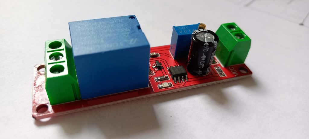
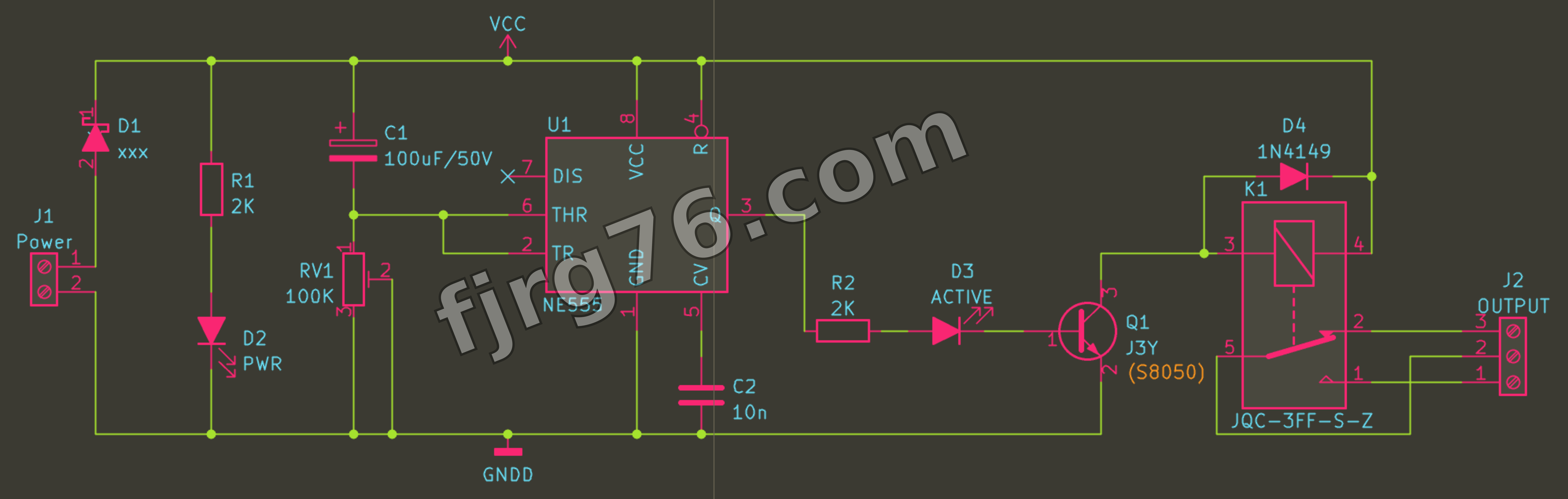
In this post I’m not gonna explain you how it works neither how it’s used, I just want to provide you its schematic so you can build yours (or for repairing purposes).
- Power supply is 12VDC.
- Transistor Q1 can be replaced for any NPN general purpose transistor, like the BC548 or so, just be careful about its pinout.
- Consider to increase the C1 value so that you get extended periods of time.
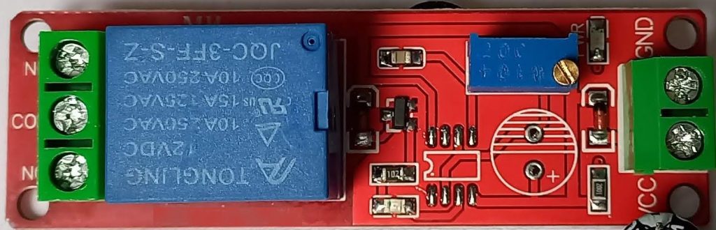
- Don’t try to remove RV1, it’s difficult as hell, you’d rather play with C1.
- For D1 you can use any suitable shottky diode, even you can try the general purspose diode 1n4007.
If you still want to buy yours, you might consider to do it through my Amazon affiliate links:
Consider to subscribe to my blog for more circuits.

Freelancer, Diseñador Senior en fjrg76.com
Soy Ingeniero Electrónico con 20+ años de experiencia en el diseño y desarrollo de productos electrónicos de consumo y a medida, y 12+ años como profesor. Egresado de la UNAM, también tengo el grado de Maestro en Ingeniería por la misma universidad.
Mi perfil completo lo puede encontrar en: https://www.linkedin.com/in/fjrg76-dot-com/
Mi perfil completo lo puede encontrar en: https://www.linkedin.com/in/fjrg76-dot-com/
Últimas entradas de Fco. Javier Rodríguez (ver todo)
- Arduino and ESP32 whims - diciembre 17, 2025
- Writing Scalable Firmware: Implementing the Command Pattern in C++ - diciembre 4, 2025
- Patrón de diseño de software Command para sistemas embebidos para los no iniciados - noviembre 30, 2025
1 COMENTARIO