How to create interchangeable software components for embedded systems. Decoupling the logic from the hardware (Episode I)
(Lee este artículo en español aquí.)
Introduction
“If you don’t use interfaces, then you haven’t understood object-oriented programming.”
(Read somewhere, really!).
A few days ago I shared with you a class (Blink) to control binary peripherals (LEDs, relays, buzzers, etc). I really liked this class, besides being very useful. However, I implemented it in a way that makes me unhappy: we must inject a function with fixed signature that interacts with the hardware.
Although I thought and designed this class in a generic way (abstraction), I used the Arduino platform for development (implementation). I/O pins on Arduino are a simple integers (0, 1, 2, …), but on all other platforms a pin is determined by a port and an integer, and even more parameters. The following line is from a source code on the NXP LPC1114 32-bits processor:
Chip_GPIO_SetPinState (LPC_GPIO, port, pin, new_state);
Should the signature of the injected function include only one parameter for the output pin to be controlled (Arduino), or should it include two parameters, one for the port and one for the terminal (as in all other platforms)? Or should we have two or more versions of the Blink class?
Keep reading to figure out how to solve such dilemma using interchangeable software components. Source code included!
Let’s look at the same problem but from a different perspective.
Imagine that you have to write a program for a processor that will be mounted on a printed circuit board. The task is simple: the card will include an LED connected directly to the processor and you must control it.
Note that controlling the LED isn’t exactly trivial (check out the method .state_machine() from my Blink class) so you’re going to need a controller class; let’s call this class Blink (much simpler, for the purposes of this explanation, than the original Blink class from the previous link).
But there is more. Your client hasn’t decided on the processor yet, and to make matters worse, they’ve already let you know that later on there will be a second version of the hardware in which it will use a terminal expander (such as the PCF8574) with the LED connected to one of its 8 pins, and perhaps a variant of the original processor will be used.
As you may have noticed, some verbs are in future tense and this implies that:
- Today you DO NOT have the first version of the card.
- Today you do NOT have the second version of the card.
- Today you DON’T know what else your client could think of (for example, controlling an LED remotely, through a UART, or changing to a 32-bit processor when the original one was 8-bit, etc).
- Today you have to get to work immediately because your client has already sign your first pay-check; that is, you can’t wait to receive the hardware to start development.
What would you do?
- Use alternative hardware to start development (Arduino UNO, ST Discovery, Raspberry Pi Pico, etc). Sounds good. Which of the 3 future scenarios are you going to start with: the on-board LED, the expander LED, or the LED used by the UART? If you program to the implementation then you’re going to end up with 3 versions of the
Blinkcontroller class!
With this solution we face three problems:
- Code repetition. You will have written 3 virtually identical versions of the source code. What if you discover an error in the logic? You would have to edit the code in all your versions!
- Uploading the program to the processor on each of the mentioned hardware platforms takes some time (have you uploaded code to the ESP32/ESP8266 chip/board?), so small changes to the program will make development time longer.
- And something very important, maybe on these platforms you don’t have access to a source code debugger (such as GDB), so the development time will be even longer.
- Write and test the driver class on your desktop computer and simulate the LED on the same PC. I like this!.
Think of the on-board LED, the expander LED, and the simulated LED on the PC as interchangeable software components. And think of the Blink controller class as a class that accepts components.
Your workflow might look like this:
- Design the interface for your future components.
- Code the
LedPCcomponent and test it on your PC while the first version of the hardware arrives. - Code, test and debug the
Blinkcontroller class on the PC using theLedPCcomponent you’ve written above. - Code, test and debug the
LedOnBoardcomponent when you receive the first version of the hardware using its compiler. - Code, test and debug the
LedXpandercomponent when you receive the second version of the hardware using its own compiler.
You’ve written 3 interchangeable software components and a single version of the Blink controller class. And please note something subtle and very important: the Blink class is hardware independent.
¡Looks like science fiction!
Interfaces
How can we achieve all this? With interfaces. An interface is a contract that establishes the behavior that the classes must implement, and if your controller class and the different components honor it, then you will be programming to the interface (as opposed to programming to the implementation).
The easiest way to write interfaces in C++ is with abstract base classes, pure virtual methods and polymorphism (I’ll briefly talk about two other ways later):
struct My_Interface
{
    virtual return_type method1( /*args_list*/ ) = 0;
    virtual return_type method2( /*args_list*/ ) = 0;
    // more virtual pure methods
};
Note that:
- Only the behavior (that is, the methods) is listed.
- All methods are pure virtual. Remember that this is how abstract base classes are written in C++.
- It has no constructor.
- There is no state to save (that is, it has no attributes).
The points above were described by the programming guru Robert C. Martin:
“1. High-level modules should not depend on low-level modules. Both should depend on abstractions.
2. Abstractions should not depend on details. Details should depend on abstractions.”
That is, in a layer-based architecture, between two layers there must be an abstraction. This intermediate layer will allow the upper or lower layer to change with minimal (or zero) effects on the system, as the following diagram shows:
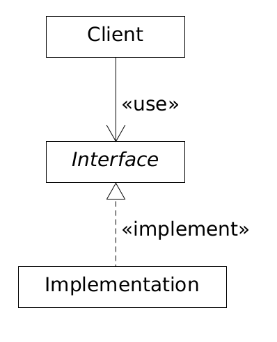
In the ongoing project in this post the abstraction layer is the interface, the components are the lower layer (implementation), and the controller class (client) is the top layer.
Point 2 states that an abstraction must contain only the functionality (methods, functions) and not details (state, attributes). Whoever wants to use the abstraction must provide the code for the interface methods (that is the implementation and the details).
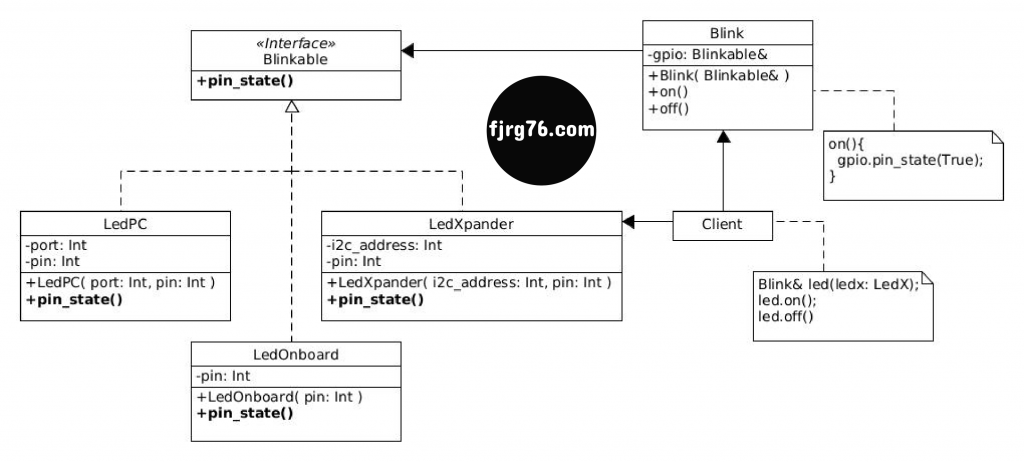
If you like UML diagramming, this diagram is more formal and represents all the elements involved in the system. In the section Development of the example we will study element by element. (If you find some errors in the below diagram, please let me know them in the comments box.)
Interface implementation
When we say that a class will implement an interface we are referring to a class that will inherit from the interface and will provide the code corresponding to the pure virtual methods of its base class:
class My_implementation : public My_Interface
{
private:
    /* some state and attributes */

public:
    My_implementation( /*args_list*/ );
    /* optional in embedded systems:*/ virtual ~My_implementation();

    return_type method1( /*args_list*/ ) override
    {
        // code that implements method1() behavior
    }

    return_type method2( /*args_list*/ ) override
    {
        // code that implements method2() behavior
    }

    /* more methods if need it */
}
In languages that don’t support components (C, C++, Java) component-oriented programming is done through interfaces, as I just described, at the binary level; that is, within the executable code itself (as opposed to dynamic libraries, for example).
Of course, the topic of components is much broader than that, but for the purposes that I have proposed myself, it is enough for me to write different implementations of the interface (the components) and the controller class (the one that receives the components). And that has exceeded my expectations by far.
Development of an example with dynamic polymorphism
We are going to solve the two problems presented in the introduction using interfaces, components and abstract base classes (they are the same problem, but from different points of view).
1 Designing the interface
Our interface consists of a single method that will activate or deactivate (turn on/off, set to 1/0, etc) a microcontroller output pin. We’re going to call it IBlinkable. The “I” stands for “Interface” and it is customary for that letter to precede the class name:
struct IBlinkable
{
   virtual void pin_state( bool new_state ) = 0;
};
2 Coding a component that will run in the PC
From the previous interface it’s time to write our first component, which will simulate the behavior of an LED on the PC:
class LedPC : public IBlinkable
{
private:
   uint32_t port; // hardware port (placeholder)
   uint8_t pin;   // hardware pin (placeholder)

public:
   LedPC( uint32_t port, uint8_t pin ) : port{port}, pin{pin}
   {
      std::cout << "LedPC::LedPC()";
   }

   // mocked behavior:
   void pin_state( bool new_state ) override
   {
      std::cout << (new_state == false ? "LedPC::OFF" : "LedPC::ON") << std::endl;
   }
};
Since we are simulating the behavior of a LED on the PC and we cannot see whether its state is on or off, instead we are going to write a message on the screen that allows us to know if the result is what we expect.
The port and pin attributes are not used here, but they show you that implementations can have as many attributes (state variables) as necessary, and that they can be initialized in the constructor. A very useful and flexible feature indeed!
3 Coding the Blink controller class
Armed with our first component, it’s time to write the class that will receive them, which I’ve been calling the controller class and I’ve named Blink:
class Blink
{
private:
   IBlinkable& gpio; // component holder

public:
   Blink( IBlinkable& new_gpio ) : gpio{new_gpio}
   {
       // if needed
   }

   void on()
   {
      gpio.pin_state( true );
   }

   void off()
   {
      gpio.pin_state( false );
   }
};
The gpio attribute is a reference to a particular implementation of the Blinkable interface; that is, here we will store the reference to the component that we connect to it. The initialization of the rest of the attributes of this class (if any) is done in the constructor.
The .on() and .off() methods are the ones that interact with the component through its reference (e.g. it calls the methods that implement the pure virtual methods of the interface).
Once we have the controller class, and at least one component, we can then start testing the magic:
int main()
{
   LedPC led_pc( 0x1234, 10 );
   Blink led( led_pc );

   led.on();
   led.off();
}
We first create an instance of the LedPC component and then we bind it to the led instance of the controller class. led is the object that acts as the client of the led_pc component and it is the one that we will be using throughout the project we are working on.
An execution of the code that we have seen so far is:
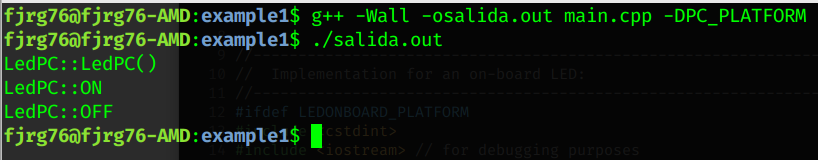
NOTE: Since I wrote all the code in a single file (for explanation purposes) I had to use some constants to establish which component I am going to compile against. In a real-world project we need to set up a solid file structure (as shown in the companion code).
Please keep in mind that we are running an LED on the desktop!
4 Coding the component that will run in the hardware
When you grab in your hands the first version of the hardware (currently, the production version) all you need to do is to write the component LedOnBoard, binding it to an instance of the controller class Blink (which is the same as in step 3, and in theory it already works correctly by now), and compile the project for the microcontroller used.
Let’s assume that the hardware is based on the ATMEGA328 microcontroller and that it works as the Arduino platform (in such the microcontroller pins are identified with an integer number only):
// Class IBlinkable as before


class LedOnBoard : public IBlinkable
{
private:
   uint8_t pin; // maybe it is an Arduino implementation

public:
   LedOnBoard( uint8_t pin ) : pin{pin}
   {
      pinMode( this->pin, OUTPUT );         // real hardware
   }


   void pin_state( bool new_state ) override
   {
      digitalWrite( this->pin, new_state ); // real hardware
   }
};


// Class Blink as before


int main()
{

   LedOnBoard led_on_board( 13 ); // (1)
   Blink led( led_on_board );     // (2)

   led.on(); // (3)
   led.off();
}
- In this particular implementation of the interface we have used the constructor to set the terminal as output.
- Then we connect the
led_on_boardcomponent to the controller class. - And finally we make the calls to the
led.on()andled.off()methods.
Both methods effectively call the LedOnboard::pin_state() method (thanks to the polymorphism), and this in turn calls the Arduino function digitalWrite() to change the state of a pin. Voila!
5 Coding the component that will run in the second hardware version
Time has passed and your client’s threat was fulfilled: the second version of the hardware is ready and it has connected the LED to one terminal of an I2C port expander (such as the PCF8574).
Fortunately at this point you are already a component expert and all you are going to do is write an implementation for this new version of the hardware:
// Class IBlinkable as before


class LedXpander : public IBlinkable
{
private:
   uint8_t i2c_address; // xpander (PCF8574) I2C address
   uint8_t pin;         // 0-7

public:
   LedXpander( uint8_t i2c_address, uint8_t pin ) : i2c_address{i2c_address}, pin{pin}
   {
      //i2c_config();
   }


   void pin_state( bool new_state ) override
   {
      uint8_t port_val = i2c_read( this->address );
      port_val = new_state==false ?
                   port_val & ~bit_mask[this->pin] :
                   port_val | bit_mask[this->pin];
       i2c_write( this->address, port_val );
   }
};


// Class Blink as before


int main()
{
   LedXpander led_xpander( 0x20, // 7bit i2c address
                           3 );  // pin on the xpander chip

   Blink led( led_xpander );

   led.on();
   led.off();
}
For this new component there isn’t much to say that hasn’t already been said. Its constructor gets the I2C address and pin number, and initializes the corresponding attributes, and perhaps initializes the microcontroller’s I2C module.
Next, the method that implements the interface, pin_state(), calls the I2C bus functions to write to the PCF8574 (or equivalent) device.
Please note that you no longer had to modify the Blink controller class, you just had to create the component and connect it to it. How cool is that?
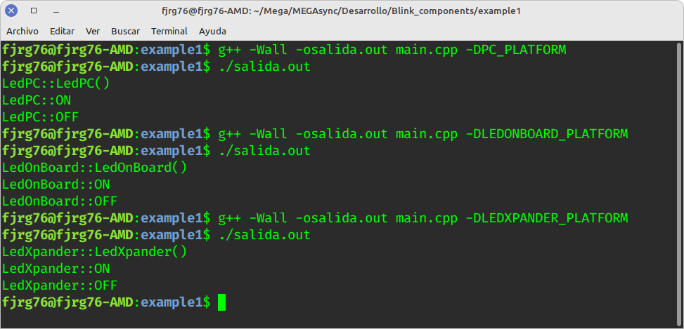
The following image shows the 3 components (all simulated for explanation purposes) being connected to the Blink controller class, and working as expected!
More components
From here you can:
- Write as many components as needed (perhaps an LED that is controlled by the UART or by Wi-Fi).
- Use the components you’ve written with different clients in different projects (classes other than Blink that require controlling an LED).
Write once and use many times!
Component Names
I’ve used different names for the different components in the development of the example; however, it does not have to be like this. If you maintain a correct organization of your project files, then you could use the same name for the different components. And if so, the magic would be more surprising!
From the main() function in an example included in the source code (you can get the link below) see that I’ve used the same name. As I introduced a more or less solid file structure, then I can name the different components the same.
Changes in the controller function
An advantage of using the abstraction layer (the interface in this project) is that if one day the logic of the Blink controller class should change (which it certainly will) you will be able to make the necessary changes easily and fast, because, on the one hand, you will only have to modify the code of the controller class (without touching the code of the components that you had written). And on the other hand, the development of the new logic can be done back on you desktop PC using the simulated LED component and perhaps the GDB debugger, without messing with the hardware!
Alternatives to dynamic polymorphism and virtual methods
“Hey, but interfaces use dynamic polymorphism and virtual methods and we’ve been told since our childhood to avoid them in embedded systems”. True, but not entirely.
Virtual methods involve a table lookup, the so called vtable, which incurs in space and time costs. However, let’s be honest: we have used pointers to functions since ever without thinking in its costs. Why should dynamic polymorphism be any different?
In our embedded systems it is unlikely to happen that you change the LedOnboard component to the LedXpander component when the program is running, the world doesn’t behave like that for us! This means that the assignment of the LedOnboard component (and for all practical purposes, any component that implements the interface) will be done only once during the life of the program:
Blink led( led_on_board ); // just once! It won't change while the program is running.
On the other hand, there is good news (more or less) if you insist on not using dynamic polymorphism. There are (at least) two other ways to write interfaces:
- With static polymorphism.
- With header files.
Just as object-oriented programming is in the programmer’s head and not in the programming language (did you know you can program with objects in C and Pascal?), interfaces are also in the programmer’s head.
An interface in C++ can be realized in several ways:
- With abstract base classes (as we have seen), making all methods in the base class pure virtual. It uses dynamic polymorphism: the link between methods and their implementations is done at runtime. This is the way I used in the example above (although it’s once in the project life, as mentioned).
- With templatized base classes. It uses static polymorphism via the CRTP C++’ pattern: the link between methods and their implementations is done at compile time. The same example that we have seen, but using this form, is the subject of a second part of this article (the Episode 2).
- With header files (.h or .hpp) through the set of function declarations. I’ll be passing you the same example we’ve developed using this solution as an addendum to this series.
Let’s now look the advantages and disadvantages of each of the different ways of writing interfaces:
- Easy to implement, but has little cost in space and uses runtime. It’s not much, but embedded systems purists might not agree in using it.
- Extremely difficult to understand, easy to implement, and almost incurs no space or time costs.
- Easy to implement, but loses the benefits and advantages of the mechanisms provided by C++ for OOP. This way is ideal if you don’t have a C++ compiler or the previous two ways don’t meet your expectations.
Regarding to the 3 previous ways of writing interfaces, the authors John and Wayne T. Taylor in their book “Patterns in the Machine (affiliate link)”, Apress, 2021, has written:
“An abstract interface does not have to be a pure virtual class in C++. An abstract interface is any interface that defines a behavior that has a deferred binding (ie, not a source time binding) for its implementation.”
(Source time binding refers to conditional compilation which doesn’t count as an interface.)
This is what I meant when I said “interfaces are in the heads of programmers”. The point is that as long as there is a contract, in whatever form, then we have an interface if it is honored.
As an introduction, I will talk about these other two ways of implementing interfaces (but remember that in Episode 2 I’ll write about interfaces using static polymorphism).
Interfaces with static polymorphism and the CRTP pattern
While dynamic polymorphism makes the link between the object and the message when the application is already running, static polymorphism binds the object and the message at compile time, and does not incur time and space costs. In exchange for?
Static polymorphism is based on a fascinating, obscure, complex, esoteric, and out of this world C++ concept known as the CRTP pattern, Curiously Recursive Template Pattern, and its implementation is worse than its name (actually the implementation is very simple once you’ve understood the concept, but that’s where the problem lies).
I hope that the examples that I am going to present to you in the second part of this series will clarify your ideas about this pattern.
Until the second part arrives, here I leave you a couple of articles that I wrote in my alternative blog and in which I dealt with this topic:
Interfaces with header files
This is perhaps the easiest way to implement interfaces, as long as the programmer(s) sticks to the established guidelines and doesn’t deviate from them. A declaration is a primitive interface, but an interface nonetheless. If you break the contract, then the compiler will reject your code.
The implementation provides the code (or codes, one per component) that satisfies declaration of the interface. Its cost in time and space is null.
Organization of project files
So far I have left out an important concept in my description: the organization of project files.
To get the most out of this way of programming components it is imperative that you maintain a project file structure that allows the coexistence of the different components at the same time (at hard disk level) and an easy and correct way of exchanging them (e.g., you can develop and test on the PC and then quickly and easily integrate it into the hardware when it’s ready).
In the following example, at the end, I’ll show you a simple file structure to give you an idea, and in the complete example you’ll find a more or less solid and consistent file structure, along the
Complete example
Here you can get a copy of the complete example that includes the controller class and the three developed components.
You will notice that I did everything in one file so as not to obscure the main point of this article and they all run on the PC. However, for a real project I insist on a correct organization of the source code.
The repository also includes the code for the statically polymorphic version, in case you want to check it out as I write the article.
Arduino
In case you want to put these ideas into practice in the Arduino framework, then you will have to abandon its (horrible) IDE and look for alternatives. Personally, I use Arduino with makefile files: Arduino-Makefile.
The problem with the Arduino IDE is that it is too dumb to handle multi-file projects, and while a couple of solutions might be to copy and paste files or create symlinks, these don’t scale well. When you start programming with components you are entering into a level that the IDE cannot handle.
Final Words
Decouple logic from hardware by programming interfaces. As you could see, interfaces are a very important concept that can be of enormous benefit in our always evolving embedded systems.
Of the many advantages that component-oriented programming I can think of, the one I like the most is having the possibility of writing the logic (almost always complex) on the desktop computer because, in addition to the speed of development, I could use TDD (Test Driven Development).
And if things don’t go right, then I can use the GDB debugger to quickly find problems. Can we do the same on hardware, such as an ARM processor with an external debugger (j-link)? Yes, but the speed of development on a PC is much higher.
I hope you’ve enjoyed this first part of this series. If you have not subscribed to my blog, do it now so that the you receive the Episode 2 immediately when it’s ready.
Affiliate links:
Este libro trata sobre diferentes formas de aplicar el desarrollo dirigido por pruebas en hardware para nuestros sistemas embebidos.
More interesting productos (afiliate links. They don’t cost you.):
- Arduino UNO original: https://amzn.to/3MH8zvx
- Arduino Nano Every: https://amzn.to/3KwNi5X
- STM32 NUCLEO-F401: https://amzn.to/3vTtrsu
- Raspberry Pi Pico, starter kit: https://amzn.to/3xZwHFk
KiCAD Printed Circuit Boards design
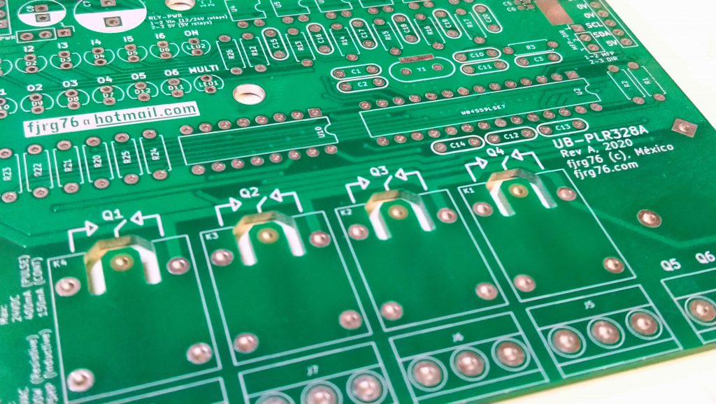
Along writing posts in my blog I also design printed circuit boards in KiCAD. Find me on Fiverr!.
Have you already heard about my course (in spanish) for Arduino in real time using FreeRTOS and the Arduino UNO or the Arduino Due boards?
Subscribe, is free!

Mi perfil completo lo puede encontrar en: https://www.linkedin.com/in/fjrg76-dot-com/
- Arduino and ESP32 whims - diciembre 17, 2025
- Writing Scalable Firmware: Implementing the Command Pattern in C++ - diciembre 4, 2025
- Patrón de diseño de software Command para sistemas embebidos para los no iniciados - noviembre 30, 2025
3 COMENTARIOS